
Lightweight quick response aerial remote sensing inertial-stabilized platform controlling system

An inertial stable platform and aviation remote sensing technology, applied in directions such as navigation through speed/acceleration measurement, can solve problems such as single working mode, achieve diverse working modes, improve reliability and safety, and prevent collisions

Active Publication Date: 2014-02-26
BEIHANG UNIV
View PDF6 Cites 0 Cited by
  • Summary
  • Abstract
  • Description
  • Claims
  • Application Information

AI Technical Summary

Problems solved by technology

[0005] The technical problem of the present invention is: to overcome the shortcomings of the single working mode of the existing aerial remote sensing inertial stabilization platform, aiming at the needs of the light and small aerial remote sensing system for fully autonomous and unmanned operation, and to provide a variety of working modes, high integration, and intelligence. Lightweight and fast response aviation remote sensing inertial stabilization platform control system

Method used


Image

  • Lightweight quick response aerial remote sensing inertial-stabilized platform controlling system
  • Lightweight quick response aerial remote sensing inertial-stabilized platform controlling system
  • Lightweight quick response aerial remote sensing inertial-stabilized platform controlling system

Examples


Embodiment Construction

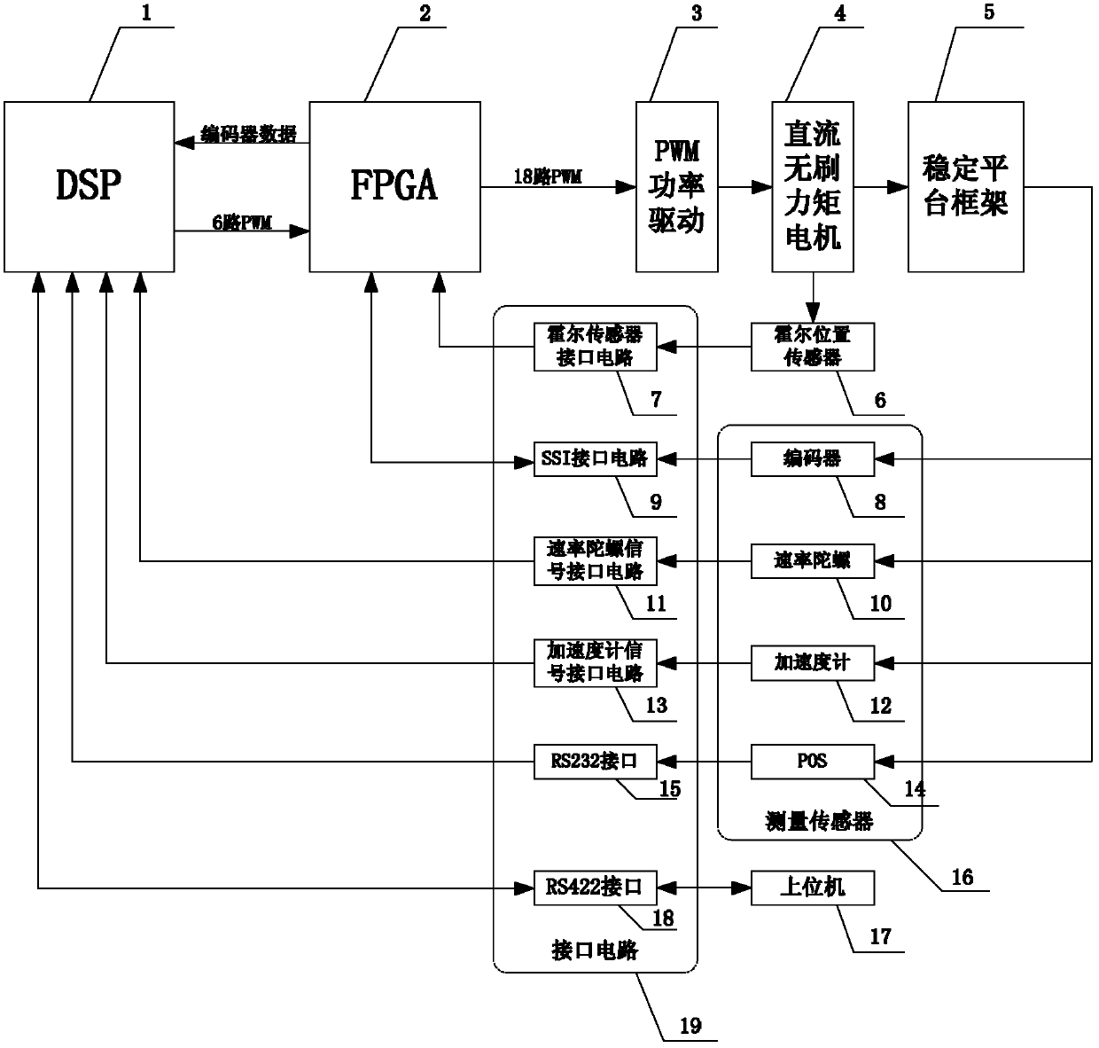
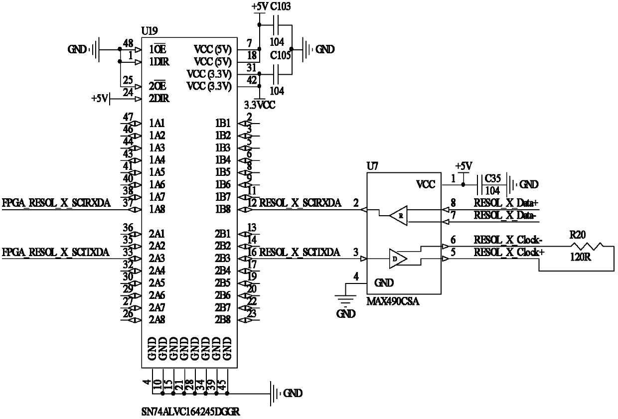
[0024] Such as figure 1 As shown, the hardware module of the present invention mainly includes a DSP module 1, an FPGA module 2, a PWM power drive module 3, a DC brushless torque motor 4, a stable platform frame 5, a measurement sensor 16, and an interface circuit 19. Wherein the stable platform frame 5 includes a roll frame, a pitch frame and an azimuth frame, the measurement sensor 16 includes three encoders 8, three rate gyroscopes 10, two accelerometers 12, and POS14, and the interface circuit 19 includes a Hall sensor interface circuit 7. SSI interface circuit 9, rate gyro signal interface circuit 11, accelerometer interface circuit 13, RS232 interface 15, and RS422 interface 18.

[0025] The present invention has two working modes: autonomous mode and combined mode. Its specific implementation is described as follows:

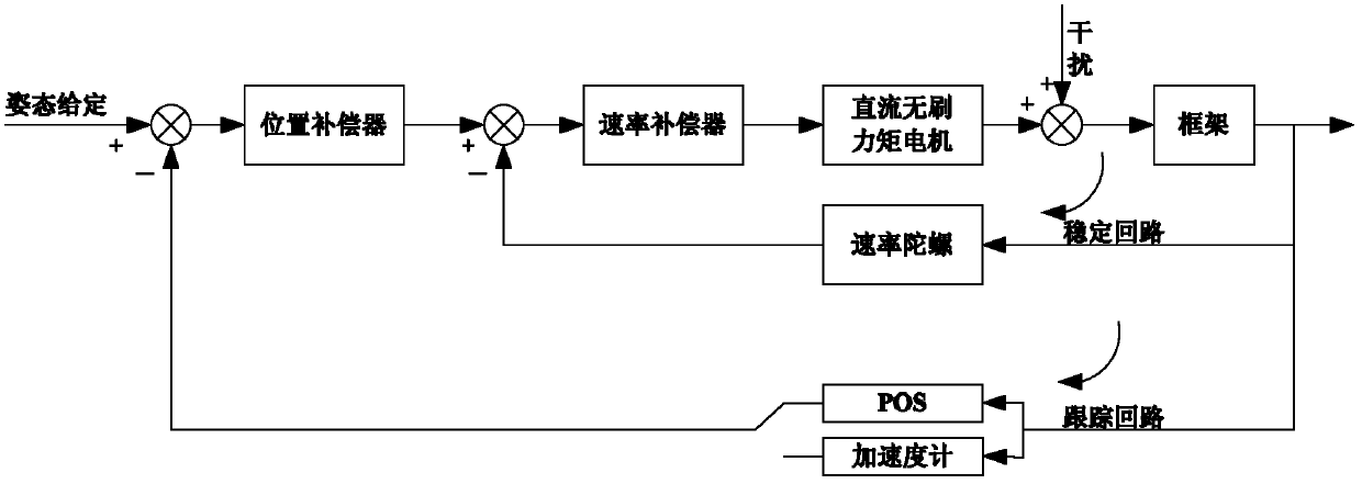
[0026] In the autonomous mode, the rate gyro signal interface circuit 11 converts the current signal output by the rate gyro 10 into a voltage signal o...


PUM


Abstract

The invention discloses a lightweight quick response aerial remote sensing inertial-stabilized platform controlling system used for carrying out initiative controlling upon triaxial frames of stabilized platforms. The system comprises a DSP module, an FPGA module, a PWM power driving module, brushless DC torque motors, a stabilized platform frame, a measuring sensor, and an interface circuit. Angular position information, angular rate information and attitude information of the frame output by the measuring sensor are acquired by the DSP module and the FPGA module through the interface circuit in real time. PID controlling algorithm is executed by the DSP module and the FPGA module, and 18 PWM signals for controlling the three brushless DC torque motors are generated. The signals are converted into voltage signals by the PWM power driving module, and the brushless DC torque motors are driven, and the frame is driven to rotate, such that the initiative controlling upon the triaxial frame is realized. According to the invention, an independent mode and a combined mode are realized, and a frame soft lock function and an independent course configuration function under the combined mode are realized. Therefore, the operation of the platform is more reliable and intelligent.

Description

technical field [0001] The invention belongs to the technical field of high-resolution earth observation, and relates to a control system of a lightweight and fast-response aerial remote sensing inertial stabilization platform, which is used for active control of the three-axis frame of a lightweight and fast-response aerial remote sensing inertial stabilization platform, and is especially suitable for light Small aerial remote sensing system and UAV-borne aerial remote sensing system. Background technique [0002] The aerial remote sensing inertial stabilization platform is one of the very important organic components of the high-resolution earth observation system. It is used to support and stabilize the remote sensing load, and can effectively isolate the influence of various disturbances in the air on the boresight stability of the remote sensing load. It is better to keep the smooth and ideal motion of the phase center of the remote sensing load. [0003] Aeronautical ...

Claims


Application Information

Patent Timeline
Patent Type & Authority Patents(China)
IPC IPC(8): G01C21/18
Inventor 钟麦英穆全起房建成赵岩李树胜
Owner BEIHANG UNIV
Learn More