Solar Corresponding Device

A solar and driving device technology, applied in the direction of position/direction control, non-electric variable control, instruments, etc., can solve the problems that hinder the commercial development of solar tracking technology, reduce the attractiveness of tracking technology, and increase the requirements of roads and foundations, etc. , to achieve the effect of convenient daily maintenance, large reduction ratio and low driving energy consumption

Active Publication Date: 2011-12-28
刘建中
View PDF8 Cites 22 Cited by
  • Summary
  • Abstract
  • Description
  • Claims
  • Application Information

AI Technical Summary

Problems solved by technology

However, most of the existing solar tracking technologies lead to high costs due to complex structures and other reasons, even exceeding 30% of the total investment of power generation devices, and the tracking itself has power consumption, and occupies more land than fixed installations. Equipment maintenance , maintenance requires additional technicians, and the risk of device operation is greater than that of fixed installations. At the same time, in order to reduce tracking costs, manufacturers are now making tracking devices larger and larger, which in turn increases wind resistance and makes installation and maintenance difficult. A series of problems, such as increased solar energy and higher requirements for roads and foundations, have greatly reduced the attractiveness of the effects produced by tracking technology, hindering the commercial development of solar tracking technology

Method used


Image

  • Solar Corresponding Device
  • Solar Corresponding Device
  • Solar Corresponding Device

Examples


Embodiment 1

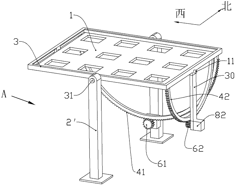
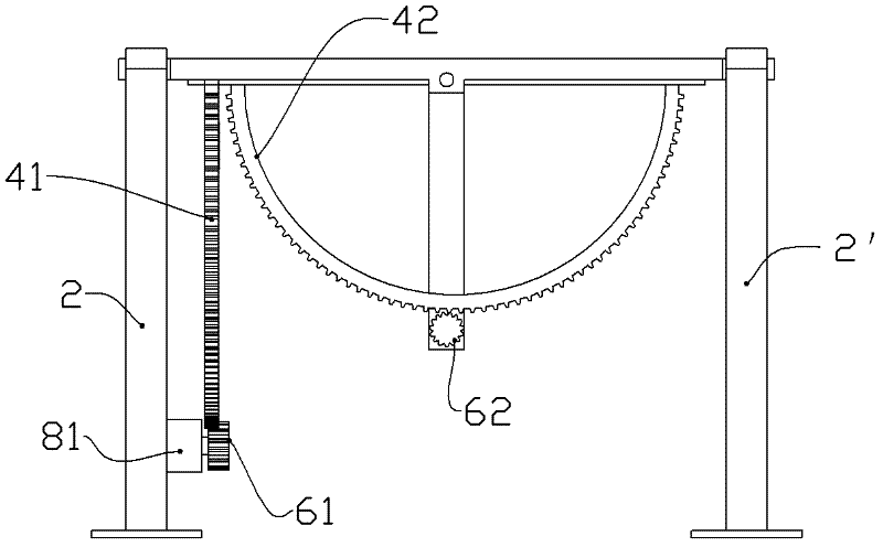
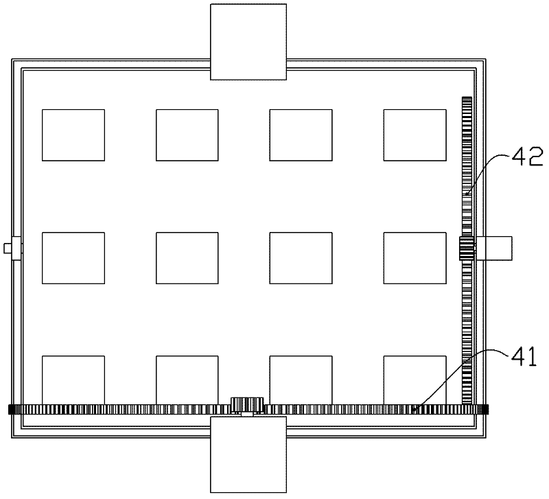
[0041] Such as Figure 1 ~ Figure 4As shown, the solar module fixing frame 1 is a rectangular frame structure made of hot-dip galvanized steel profiles through welding or bolting, and solar panels can be fixed on the solar module fixing frame. The rotating support frame 3 is a rectangular frame composed of four channel steel bolts. The solar module fixing frame 1 can just fall into the frame of the rotating supporting frame 3 and is welded in the middle of the left and right sides of the solar module fixing frame 1 respectively. The pitch angle rotation axis A11 and the pitch angle rotation axis B (corresponding to the second axis series in the content of the invention and the claims) have shaft holes at corresponding places on the left and right sides of the rotating support frame 3, and pitch angle bearings are respectively installed in the shaft holes Combination A and pitch angle bearing combination B, the solar module fixing frame 1 and the rotating support frame 3 form a...

Embodiment 2

[0054] Such as Figure 5 As shown, the difference from Embodiment 1 is that there is a positioning structure on the rigid arc body 42' of the driving member corresponding to the pitch angle, and the positioning structure is positioning holes 44 (or positioning grooves) evenly distributed on the rigid arc body 42' Array, so that it has the function of adjusting the spatial position and fixing the rigid arc body 42' (at least one end of the rigid arc body 42' is connected to the solar module fixing frame 1). The position corresponding to the positioning hole 44 (or positioning groove) on the top of the additional rod 30 and the rigid arc body 42' is provided with a fixing hole or a fixing groove; a positioning pin 45 (round pin) can be inserted in the positioning hole 44 and the fixing hole Between them, the rigid arc body 42' and the additional rod 30 of the rotating support frame can be locked together. The positioning hole 44, the fixing hole and the positioning pin 45 form a...

Embodiment 3

[0059] Such as Figure 6 , Figure 7 As shown, the difference from Embodiment 1 is that: the left and right angles correspond to the rigid arc in the drive component is replaced by a transmission rope, including the first transmission rope 51 and the second transmission rope 52; the pitch angle corresponds to the rigid arc in the drive component It is replaced by a transmission rope, including a third transmission rope 53 and a fourth transmission rope 54 .

[0060] The first driving device 81 comprises a motor and a worm gear reducer. On the output shaft of the worm gear reducer, a sheave 9 matched with a transmission rope is installed. The diameter gradually changes from the middle to the sides. There are two first helical guide grooves 91 and second helical guide grooves 92 that are symmetrical about the middle section of the sheave on the sheave cylindrical surface. The direction of rotation of the two helical guide grooves is opposite. Need to design. The first transm...


PUM


Abstract

The invention relates to a sunlight corresponding apparatus, which comprises a solar energy assembly mount, a raised support bracket, a rotating support framework, a left-and-right angle corresponding driving member and a pitch angle corresponding driving member. The solar energy assembly mount is hinged on the rotating support framework that is hinged on the raised support bracket; and accurate tracking on sunlight is realized on the basis of coordinated movements of the left-and-right angle corresponding driving member and the pitch angle corresponding driving member. According to the invention, the apparatus has a simple and reasonable structure; energy consumption for running is low; and the running accuracy is high; besides, the apparatus is easy to control and is convenient for installation and daily maintenance.

Description

technical field [0001] The invention relates to the technical field of solar energy utilization equipment, in particular to a sunlight corresponding device capable of biaxially tracking sunlight. Background technique [0002] Due to the increasing depletion of fossil energy, and the environmental pollution and greenhouse effect caused by its production and use are becoming more and more serious, the development and utilization of new energy has attracted more and more attention from all countries. Among them, solar energy, as a new type of energy that is efficient, clean, widely distributed, and almost infinitely usable, attracts people to gradually increase investment in its research and development. However, in terms of solar energy utilization, especially in the field of photovoltaic power generation: low utilization rate and high power generation cost are still common problems. This is mainly manifested in the following two aspects: first, because the photovoltaic cells...

Claims


Application Information

Patent Timeline
Patent Type & Authority Applications(China)
IPC IPC(8): G05D3/00
Inventor 刘建中
Owner 刘建中
Why Eureka
Try Eureka