A method for forming multi-conductor parallel winding components

A winding element and molding method technology, which is applied in the field of molding multi-conductor parallel winding elements of aeronautical generators, can solve the problem of imperfect manufacturing technology of multi-conductor parallel winding elements, difficulty in meeting the motor's requirements for winding embedded wires, and poor separation of conductors. It is easy to popularize and apply, improve the insulation performance and heat dissipation of the end, and the overall shape consistency is good.

Inactive Publication Date: 2011-12-28
SHAANXI AVIATION ELECTRICAL
View PDF4 Cites 6 Cited by
  • Summary
  • Abstract
  • Description
  • Claims
  • Application Information

AI Technical Summary

Problems solved by technology

During the manufacturing of armature winding components and the parting operation of component embedded wires, the production process of flat copper wires with too large cross-sectional area is poor, and it is difficult to meet the needs of motors for the embedded wires of windings. Therefore, the main When the stator and the armature winding of the DC motor need flat copper wires with too large cross-sectional area to make the armature winding components, two or more conductors are usually used in parallel to meet the embedded wire requirements.
[0003] At present, the manufacturing process technology of multi-conductor parallel winding components is not perfect. After the armature winding components produced by multi-conductor parallel connection are drawn and formed with pull-type fixtures, there are inconsistent deformations of the conductors at the ends of the winding components. Separation phenomenon, and the separation degree of each conductor is not exactly the same
The stator and rotor assembly of the motor uses parallel winding elements with separated end conductors for wire embedding, which will cause a series of problems such as difficulty in inserting the elements into the slot, mutual interference between adjacent elements at the end of the winding, damage to the conductor insulation, and large size of the end of the winding.

Method used


Image

  • A method for forming multi-conductor parallel winding components
  • A method for forming multi-conductor parallel winding components
  • A method for forming multi-conductor parallel winding components

Examples


Embodiment Construction

[0023] Now in conjunction with embodiment, accompanying drawing, the present invention will be further described:

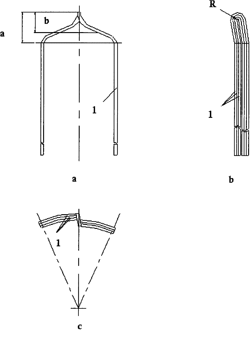
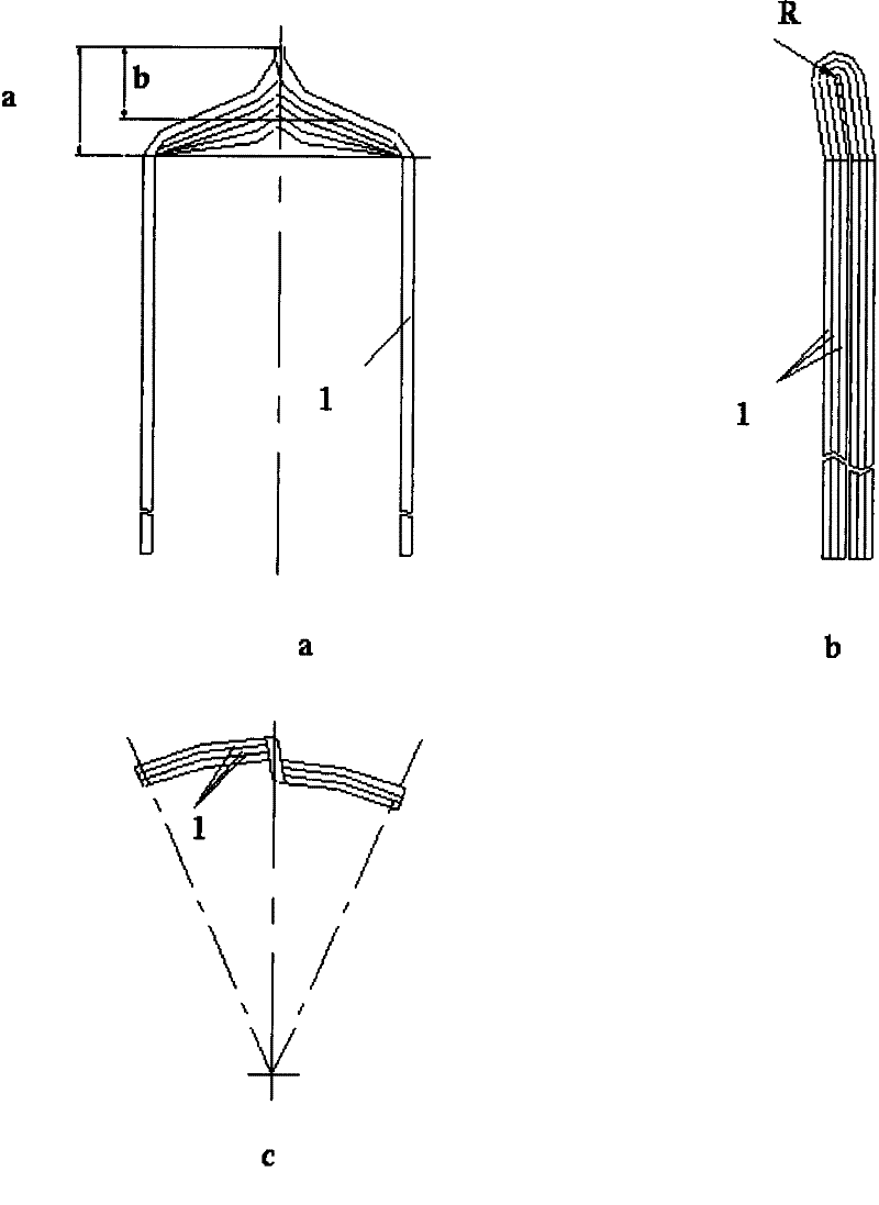
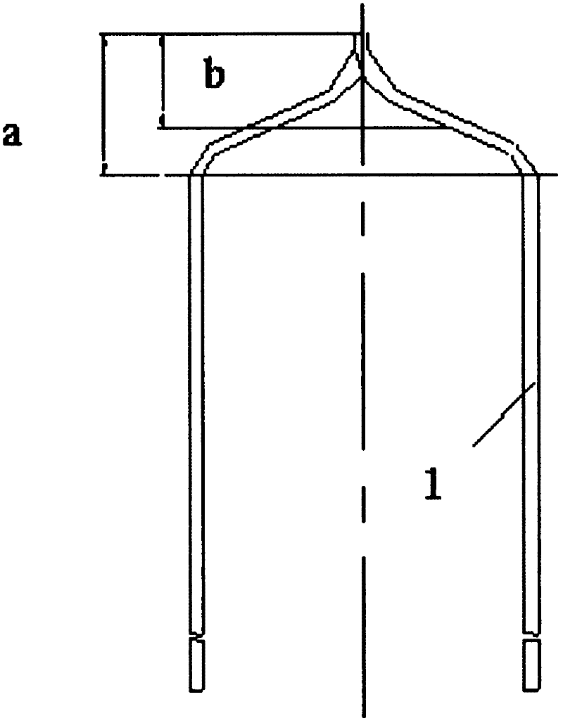
[0024] A main generator stator assembly of a 60kW alternator, the winding of which uses 54 pieces of QYB-2 / 220 polyimide enamelled flat copper wires to form a parallel winding element composed of three parallel winding elements, each conductor The specification of the element is 1.6X2.36, and the process method of the present invention is adopted for the three-conductor parallel winding element in the actual production of the aviation generator:

[0025] Step 1: Select QYB-2 / 220 polyimide enamelled flat copper wire according to the material required by the drawing of the motor winding component, and cut the material according to the size L=680mm and the quantity of 162 pieces;

[0026] Step 2: Grind rounded corners at both ends of a single wire, remove burrs, and then straighten;

[0027] Step 3: Connect 3 single wires in parallel, and use insulating 92 tape to ...


PUM


Abstract

The invention relates to a forming method of a multi-conductor parallel winding element. The forming method provided by the invention is technically characterized by comprising the following steps: connecting N solid wires in parallel, and overlapping and fixing the middle parts of the solid wires by use of insulating tapes so as to form an integral wire; bending the integral wire into a U shape and dismantling the insulating tapes; and performing 1/2 overlapping by taking the bent part of the U shape of the integral wire as a center and performing drawing formation according to winding element chart requirements. The multi-conductor parallel winding element produced by the method provided by the invention has the advantages that the end socket of the element has no conductor separation phenomenon, the integral shape consistency is good and no conductor insulation damage is caused. When the stator/rotor winding of a motor is subjected to wire inserting, the element can be put into a groove easily, the size of a winding head after wire inserting is small, and the end sockets of the element are uniformly arranged in order, so that the insulation damage caused by squeezing and collision among conductors at the winding head of the motor winding being subject to wire inserting can be avoided, the turn-to-turn short circuit fault of the motor winding can be effectively prevented from being caused, and the insulating property of the motor winding and the heat dissipation performance of the winding head are improved.

Description

technical field [0001] The invention relates to a forming method of a multi-conductor parallel winding element, which belongs to the motor manufacturing technology and relates to a forming technology of an aviation generator multi-conductor parallel winding element. Background technique [0002] During the design and manufacture of aviation motors, the stator and rotor windings of high-power motors mostly use enamelled flat copper wires with large cross-sectional areas or armature winding components made of wrapped flat copper wires for embedded wires. During the manufacturing of armature winding components and the parting operation of component embedded wires, the production process of flat copper wires with too large cross-sectional area is poor, and it is difficult to meet the needs of motors for the embedded wires of windings. Therefore, the main For stators and armature windings of DC motors, when flat copper wires with large cross-sectional areas are required to make a...

Claims


Application Information

Patent Timeline
Patent Type & Authority Applications(China)
IPC IPC(8): H02K15/085H02K15/09
Inventor 张会强李建辉王煜
Owner SHAANXI AVIATION ELECTRICAL
Why Eureka
Try Eureka