
Electromagnetic induction heating device and method thereof

An electromagnetic induction heating and electric energy technology, applied in induction heating, induction heating control, etc., can solve the problems of heating power and efficiency reduction, inconvenience, high cost, etc., and achieve good transient performance and steady-state performance, high precision and response sensitivity , High heating efficiency

Active Publication Date: 2011-12-28
STATE GRID CORP OF CHINA +1
View PDF3 Cites 22 Cited by
  • Summary
  • Abstract
  • Description
  • Claims
  • Application Information

AI Technical Summary

Problems solved by technology

Although the full bridge design can output high power, the design of the control circuit is complex, the failure rate is high, and the cost is also high. Many subsequent improvements use single-tube tuning circuits. Although the failure rate is reduced, the heating power and efficiency also increase. decrease
[0004] This shows that the above-mentioned existing electromagnetic induction heater obviously still has inconvenience and defects in structure and use, and needs to be further improved urgently.
In order to solve the problems of electromagnetic induction heaters, relevant manufacturers have tried their best to find a solution, but no suitable design has been developed for a long time, and there is no suitable structure for general products to solve the above problems. Obviously, it is a problem that relevant industry players are eager to solve.

Method used


Image

  • Electromagnetic induction heating device and method thereof
  • Electromagnetic induction heating device and method thereof
  • Electromagnetic induction heating device and method thereof

Examples


Embodiment Construction

[0043] In order to further explain the technical means and effects of the present invention to achieve the intended purpose of the invention, the specific implementation, structure and characteristics of the electromagnetic induction heating device and its method according to the present invention will be described below in conjunction with the accompanying drawings and preferred embodiments. and its efficacy are described in detail below.

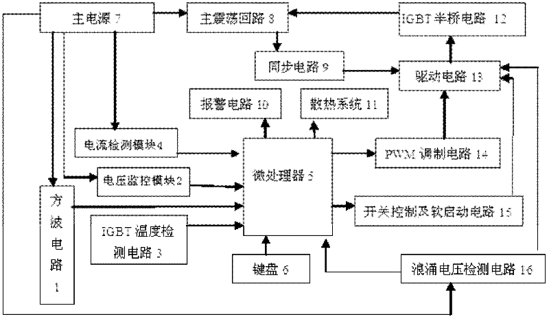
[0044] Such as figure 1As shown, the electromagnetic induction heating device includes a microprocessor 5, a keyboard 6, a main power supply 7, a main oscillation circuit 8, a synchronization circuit 9, an alarm circuit 10, a cooling system 11, an IGB half-bridge circuit 12, a drive circuit 13, a modulation circuit and Protection module, the protection module includes a current detection module 4, a voltage monitoring module 2, an IGBT temperature detection circuit 3 and a surge voltage detection circuit 16, the modulation circuit includes...


PUM

PropertyMeasurementUnit
Resonant frequencyaaaaaaaaaa

Abstract

The invention relates to an electromagnetic sensing heating device and a method thereof. The electromagnetic sensing heating device comprises a microprocessor, a modulation circuit, a driving circuit, an insulated gate bipolar transistor (IGBT) half-bridge circuit, a main oscillation circuit and a synchronizer circuit, wherein the input end of the modulation circuit is connected with an input / output (I / O) port of the output end of the microprocessor, and the output end of the modulation circuit is connected with the driving circuit; the output end of the driving circuit is connected with the control end of the IGBT half-bridge circuit; the output end of the IGBT half-bridge circuit is connected with the control end of the main oscillation circuit; and the input end of the synchronizer circuit is connected with the main oscillation circuit in serial, and the output end of the synchronizer circuit is connected with the driving circuit. The heating efficiency of the heating device is higher than that of a traditional half-bridge circuit. The improved half-bridge circuit is connected with an inversion circuit in serial, so the cost of a full-bridge circuit is greatly reduced. A control strategy combining a constant-power temperature control method and a temperature control method is adopted, so good transient-state performance and good stable performance can be realized, and higher precision and higher reaction sensitivity can be realized.

Description

technical field [0001] The invention relates to a heating device, in particular to a half-bridge serial inverter electromagnetic heating device and a method thereof. Background technique [0002] Electromagnetic induction heating technology originated in Germany and was applied in the industrial sector in the early 20th century. Since it was put into use, due to its advantages of high efficiency, low energy consumption, fast heating speed, easy control of heating area, clean and pollution-free, and easy automation, it has developed rapidly in just 100 years. For example, 1 / 4 of the heating equipment in the United States in 1976 was based on electromagnetic induction heating technology, and the installed power has nearly tripled in the past 30 years. Germany has long transitioned to a period dominated by electromagnetic induction heating and natural gas heating. In recent years, Japan's manufacturing plants have used induction heating equipment for more than 40%, and are co...

Claims


Application Information

Patent Timeline
IPC IPC(8): H05B6/06
Inventor 张金波宋佳佳孙继强黎胜邵通广陈振娇
Owner STATE GRID CORP OF CHINA
Learn More