Method and apparatus for conveying material from a combustion boiler

A technology for burning fuel and boilers, applied in the field of material devices

Inactive Publication Date: 2011-12-28
CLYDE BERGEMANN GMBH
View PDF6 Cites 1 Cited by
  • Summary
  • Abstract
  • Description
  • Claims
  • Application Information

AI Technical Summary

Problems solved by technology

[0005] However, it should be noted in this structure that a considerable structural space usually has to be provided for this

Method used


Image

  • Method and apparatus for conveying material from a combustion boiler
  • Method and apparatus for conveying material from a combustion boiler
  • Method and apparatus for conveying material from a combustion boiler

Examples


Embodiment Construction

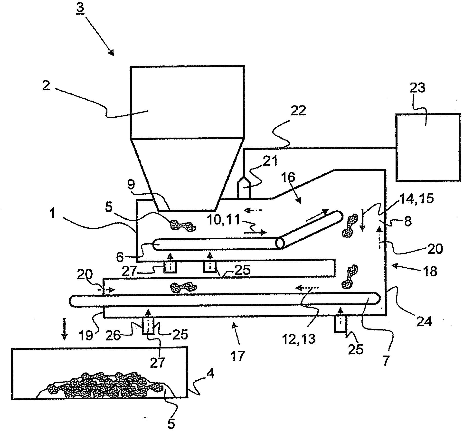
[0037] exist figure 1 A schematic side view of a first preferred embodiment of the device 1 according to the invention is shown in . The device 1 is arranged below a combustion boiler 2 in which fuel, for example refuse and / or fossil fuels such as coal, is combusted. The device 1 together with the combustion boiler 2 forms a plant 3 which is suitable for initially burning fuel and then transporting it away, and depositing the resulting material 5 in a container 4 . exist figure 1 The device 1 shown in is composed of a first conveyor belt 6 and a second conveyor belt 7 as well as a diverting device 8 . The material 5 discharged on the bottom side of the combustion boiler 2 (on the bottom mouth) passes through the outlet 9 onto the first conveyor belt 6 . From there, the material is guided by the first conveyor belt 6 in the direction of the first arrow 10 in the direction of the deflection device 8 . In the device 1 shown, the deflection device 8 is formed particularly simp...


PUM


Abstract

The invention relates to a method and a device (1) for conveying hot material (5) from a combustion boiler (2), said device comprising at least one housing (24), at least one conveyor belt (6) and at least one diverting device (8) wherein at least one conveyor belt (6) conveys the material (5) first in a first horizontal direction component (11) and after passing through a diversion device (8) in at least one second horizontal direction deviating therefrom Component (13) delivery. Furthermore, the material (5) with the first directional component (11) is always separated from the material (5) with the second directional component (13) outside the deflection device (8) by the housing (24), And, said first directional component (11) and said second directional component (13) form an angle (2) of 135° to 180°.

Description

technical field [0001] The invention relates to a device and a method for conveying material from a combustion boiler. The invention applies in particular to plants having at least one combustion boiler, for example plants for burning fossil fuels and / or waste incineration plants. Furthermore, the invention also relates to a corresponding installation having at least one combustion boiler and a device arranged below the combustion boiler. Background technique [0002] The conveying of material here involves the removal of slag, ash or combustion residues, referred to below as "material". In this context, it is of particular interest, on the one hand, to achieve a targeted solidification or hardening of the hot, partially still molten material, so that in particular its conveyance or further processing after discharge from the combustion boiler is possible. Furthermore, it is also desirable to utilize the energy in the hot material and thus increase the overall efficiency o...

Claims


Application Information

Patent Timeline
Patent Type & Authority Applications(China)
IPC IPC(8): F23J1/06F23J1/02
CPCF23J2900/01009F23J2900/01007F23J2900/01002F23J1/02F23J1/06
Inventor 拉法埃尔·莫雷诺鲁埃达杰夫·胡德森
Owner CLYDE BERGEMANN GMBH
Why Eureka
Try Eureka