Method for automatically detecting bending of injector steel needles by using machine vision system

A machine vision system and automatic detection technology, which is applied in the direction of optical testing for flaws/defects, sorting, etc., can solve the problems of inability to guarantee the quality of product qualification rate inspection, low monitoring speed, and high labor intensity, and achieve the goal of reducing inspection labor intensity Effect

Active Publication Date: 2012-01-04
WUXI ZHONGWANG 4D TECH
View PDF4 Cites 14 Cited by
  • Summary
  • Abstract
  • Description
  • Claims
  • Application Information

AI Technical Summary

Problems solved by technology

[0004] Aiming at the existing problems that the online detection of the curved needle of the syringe steel needle relies on manual detection, the workers are prone to visual fatigue, the labor intensity is high, the product qualification rate and detection quality cannot be guaranteed, and the monitoring speed is

Method used


Image

  • Method for automatically detecting bending of injector steel needles by using machine vision system
  • Method for automatically detecting bending of injector steel needles by using machine vision system
  • Method for automatically detecting bending of injector steel needles by using machine vision system

Examples


Embodiment 1

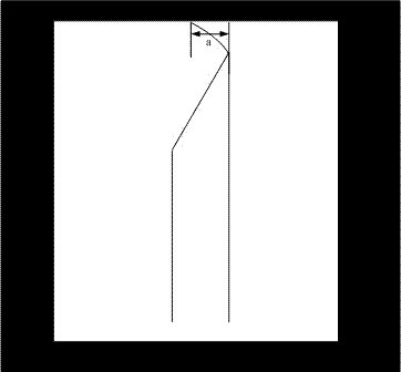
[0032] Embodiment 1, to the detection of needle tip outward bending product:

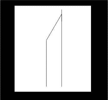
[0033] Such as figure 2 The image of needle tip curvature is shown, in which the curved part of the upper right part of the needle tip is the visual figure of the needle tip.

[0034] Fix the Basler ACA640-100GM industrial camera on the side of the steel needle, the distance between the camera and the side of the steel needle is about 20mm, use the Schneider 50 times zoom zoom lens, adjust the focal length to 16mm, and adjust the aperture to the maximum value, The exposure time was adjusted to 0.41ms. The detection accuracy of needle tip outward bending is set to 0.01mm, and the maximum normal lateral bending value of qualified products is set to 0.05mm. A special white fiber optic point light source is used to irradiate from the opposite side of the camera (backlight), and a semi-closed metal frame is used to shield the influence of stray light from the outside, so as to obtain a visual image mo...

Embodiment 2

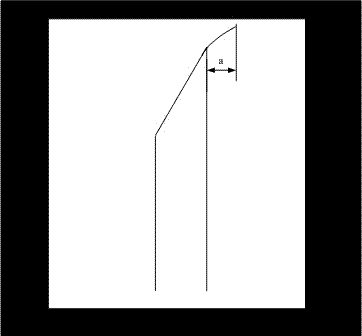
[0039] Embodiment 2, to the detection of needle tip incurved product:

[0040] Such as image 3 The image of needle tip curvature is shown, in which the curved part of the upper right part of the needle tip is the visual figure of the needle tip.

[0041]Fix the Basler ACA640-100GM industrial camera on the side of the steel needle, the distance between the camera and the side of the steel needle is about 20mm, use the Schneider 50 times zoom zoom lens, adjust the focal length to 16mm, and adjust the aperture to the maximum value, The exposure time was adjusted to 0.41ms. The detection accuracy of the steel needle looper is set to 0.01mm, and the maximum normal transverse bending value of qualified products is set to 0.05mm. A special white fiber optic point light source is used to irradiate from the opposite side of the camera (backlight), and a semi-closed metal frame is used to shield the influence of stray light from the outside, so as to obtain a visual image more stably...


PUM


Abstract

The invention provides a method for automatically detecting the bending of injector steel needles by using a machine vision system. The method comprises the following steps of: setting transverse bending values of needle points of the steel needles to be detection parameters; setting detection accuracy and qualified ranges of different detection parameters according to requirements of users; starting a camera by using external trigger and control signals to shoot pictures of the steel needles operated on line in real time, and transmitting the shot pictures to a computer for detection; processing the pictures by using the computer by a picture algorithm; extracting the pictures in which the steel needles are bent, and computing the transverse bending values of two bending needles; and judging whether a product is a qualified product or a waste product through the computed transverse bending values, and eliminating the waste product from a specified material outlet through the externaltrigger and control signals. By the method, the injector steel needles can be detected at high accuracy and high speed, and the yield of the product can be effectively ensured.

Description

technical field [0001] The invention relates to the technical field of on-line detection by using a machine vision system, in particular to a method for automatically detecting whether a steel needle of a syringe is bent or not at a production site of a steel needle of a syringe by using a machine vision system. Background technique [0002] In the assembly workshop of syringe steel needles in assembly line operation, it is necessary to conduct online detection of steel needle bending (that is, whether the needle tip of the steel needle is bent). In the prior art, the on-line detection of steel needle loopers relies on manual use of a special magnifying glass for detection, and about 80 people are set up next to the steel needle production machine to detect and process the steel needle loopers, and the products are classified into qualified products according to the detection results (such as the lateral bending value of the outer bend < 0.05mm, the lateral bending value ...

Claims


Application Information

Patent Timeline
IPC IPC(8): B07C5/342G01N21/95
Inventor 董仲伟
Owner WUXI ZHONGWANG 4D TECH
Why Eureka
Try Eureka