
Pile head large-diameter steel bar straightening device

A technology of large-diameter steel bars, which is applied in the field of large-diameter steel bar straightening devices at pile heads, can solve problems such as difficulty in straightening large-diameter steel bars, labor-intensive large-diameter steel bars, and low efficiency, so as to save manpower, increase production efficiency, and mechanize high degree of effect

Active Publication Date: 2012-01-04
中建三局集团(深圳)有限公司 +1
View PDF4 Cites 6 Cited by
  • Summary
  • Abstract
  • Description
  • Claims
  • Application Information

AI Technical Summary

Problems solved by technology

This straightening method is extremely laborious and inefficient for large-diameter steel bars
To sum up, most of the methods of straightening the steel bars at the pile head are manually straightened at present. Such methods are labor-intensive and inefficient, and it is extremely difficult to straighten the large-diameter steel bars.

Method used


Image

  • Pile head large-diameter steel bar straightening device
  • Pile head large-diameter steel bar straightening device
  • Pile head large-diameter steel bar straightening device

Examples


Embodiment 1

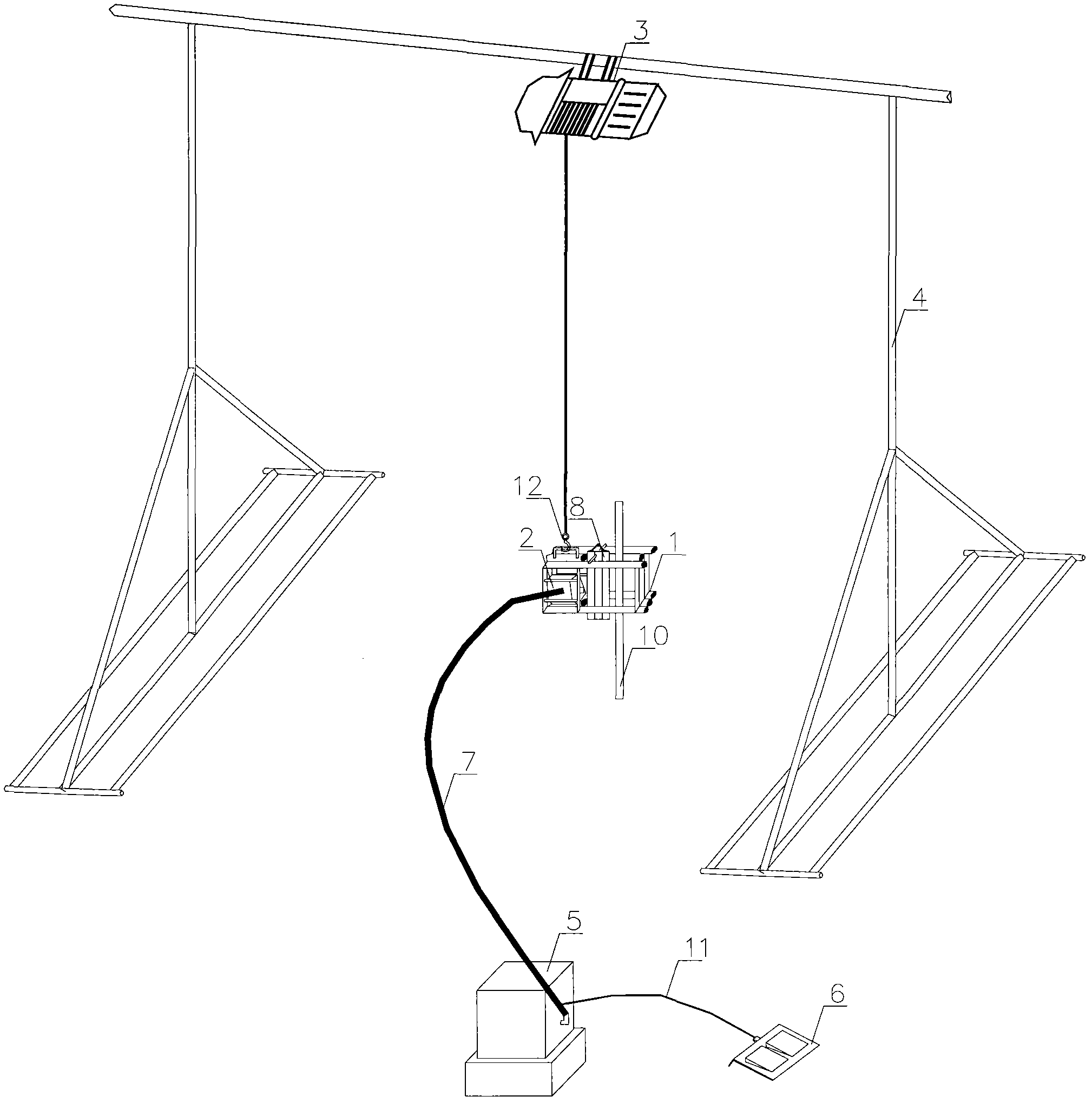
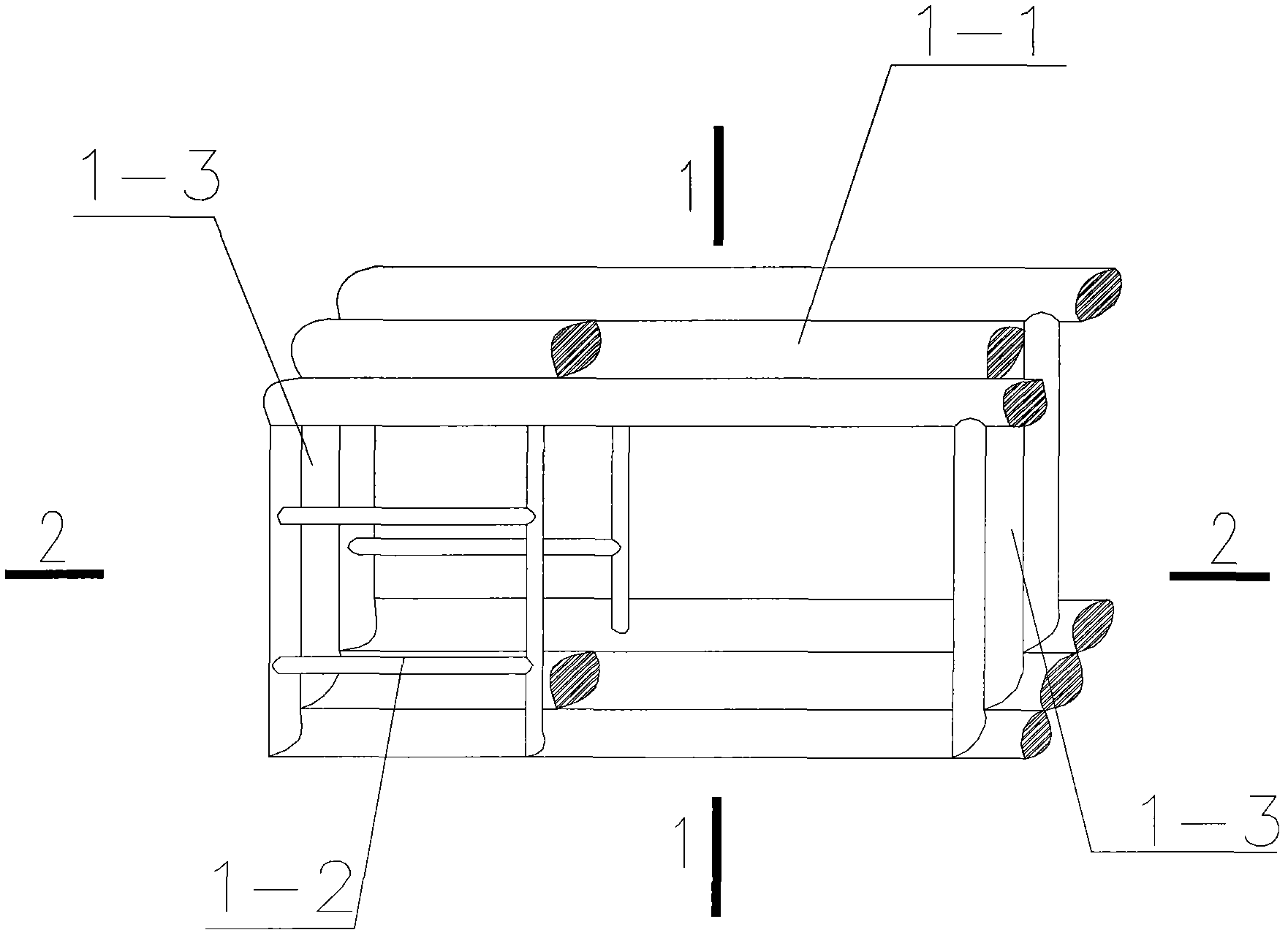
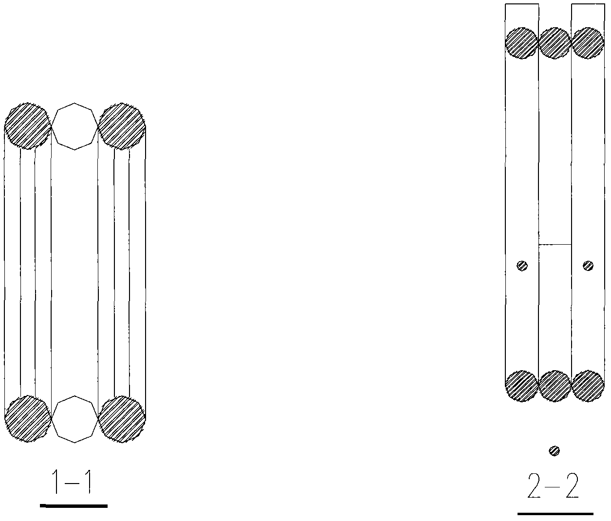
[0027] Embodiment one: see Figure 1-Figure 8 , Figure 10 In the figure, a large-diameter steel bar straightening device at the pile head includes a bracket, a lifting mechanism, a hydraulic straightening mechanism, a hydraulic power and a control system, and the hydraulic straightening mechanism includes a straightening frame, a movable pressure rod, and a The hydraulic cylinder in the straightening frame, the middle part of the straightening frame is provided with a straightened steel bar insertion hole transparent up and down, the movable pressure rod is inserted into the straightened steel bar insertion hole, and the hydraulic cylinder piston rod The direction of travel is perpendicular to the insertion hole of the straightened steel bar. The lifting mechanism is an electric hoist, and the wire rope hook of the electric hoist is connected with the adjustment frame. The hydraulic power and control system includes a hydraulic pipe, a hydraulic pump station, and an electri...

Embodiment 2

[0028] Embodiment two: see Figure 1-Figure 7 , Figure 9 , Figure 10 A large-diameter steel bar straightening device at a pile head, including a bracket, a lifting mechanism, a hydraulic straightening mechanism, a hydraulic power and a control system, and the hydraulic straightening mechanism includes a straightening frame, a movable pressure rod, and is installed in the straightening frame The middle part of the straightening frame is provided with a straightened steel bar insertion hole transparent up and down, the movable pressure rod is inserted into the straightened steel bar insertion hole, and the traveling direction of the piston rod of the hydraulic cylinder It is perpendicular to the insertion hole of the straightened steel bar. The lifting mechanism is an electric hoist, and the wire rope hook of the electric hoist is connected with the adjustment frame. The hydraulic power and control system includes a hydraulic pipe, a hydraulic pump station, and an electric ...


PUM


Abstract

The invention discloses a pile head large-diameter steel bar straightening device, comprising a bracket, an elevating mechanism, a hydraulic straightening device and a hydraulic power and control system. The hydraulic straightening mechanism comprises a straightening frame, a movable compression bar, and a hydraulic cylinder mounted in the straightening frame, wherein the middle part of the straightening frame is provided with a straightened steel bar insertion hole which is a through hole from top to bottom, the movable compression bar is inserted into the straightened steel bar insertion hole, and the travel direction of a piston rod of the hydraulic cylinder is perpendicular to the straightened steel bar insertion hole. In the whole steel bar straightening process, except for a carrying instrument and an operating instrument, the rest parts of the pile head large-diameter steel bar straightening device are mechanically operated, so that the pile head large-diameter steel bar straightening device has high degree of mechanization and can greatly save labor force and improve work efficiency.

Description

technical field [0001] The invention relates to a pile head steel bar straightening tool, in particular to a pile head large-diameter steel bar straightening device. Background technique [0002] After the construction of engineering piles on various construction sites is completed, during the construction process such as earthwork excavation, the steel bars at the pile head will be collided and bent and deformed. The traditional methods of straightening pile head steel bars include freehand straightening, steel pipe straightening, and pile head steel bar straightening. Freehand straightening has low straightening accuracy for steel bars with small diameters (multiple adjustments are required for the same bending point), and the straightening effect is poor. Using steel pipes to straighten is extremely laborious and time-consuming for steel bars with larger diameters, and when the spacing between steel bars is too small, it will not be possible to operate due to the obstruc...

Claims


Application Information

Patent Timeline
IPC IPC(8): B21F1/02
Inventor 胡杨立高波梁修青卢鲲鹏
Owner 中建三局集团(深圳)有限公司
Learn More