Heat exchanger tube used for evaporator

A technology of heat exchange tubes and evaporators, applied in heat exchange equipment, tubular elements, heat transfer modification, etc., can solve problems such as the inability to guarantee the cavity structure, achieve reduced strength, increase activity, and increase boiling heat transfer coefficient Effect

Inactive Publication Date: 2012-01-04
JIANGSU CUILONG PRECISION COPPER TUBE CORP
View PDF14 Cites 11 Cited by
  • Summary
  • Abstract
  • Description
  • Claims
  • Application Information

AI Technical Summary

Problems solved by technology

[0006] However, it is not limited to the structure of the outer fins outside the heat exchange tube of the evaporator in the published documents cited above, which cannot guarantee the cavity structure It has the ability to trap residual steam and maintain the activity of holes in a large range of heat flux density changes

Method used


Image

  • Heat exchanger tube used for evaporator
  • Heat exchanger tube used for evaporator
  • Heat exchanger tube used for evaporator

Examples


Embodiment 1

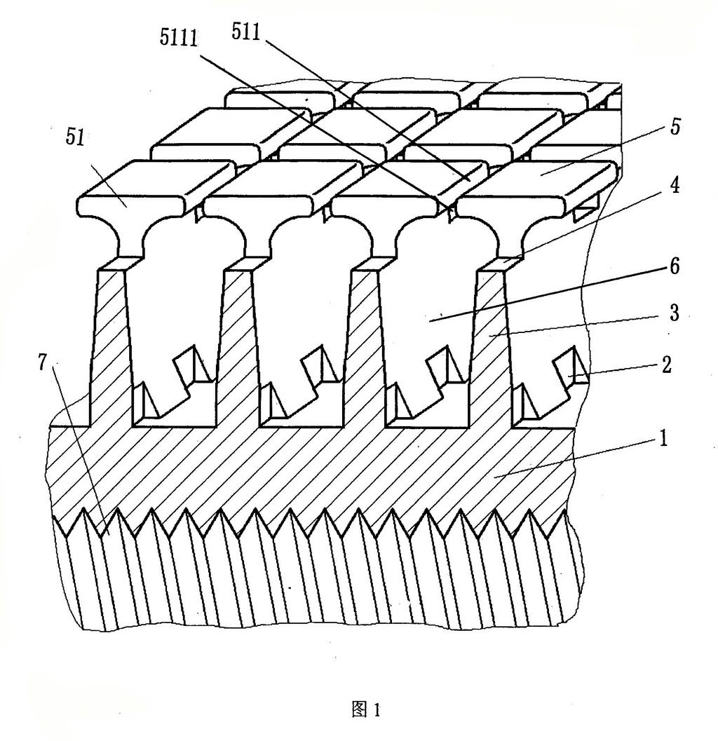
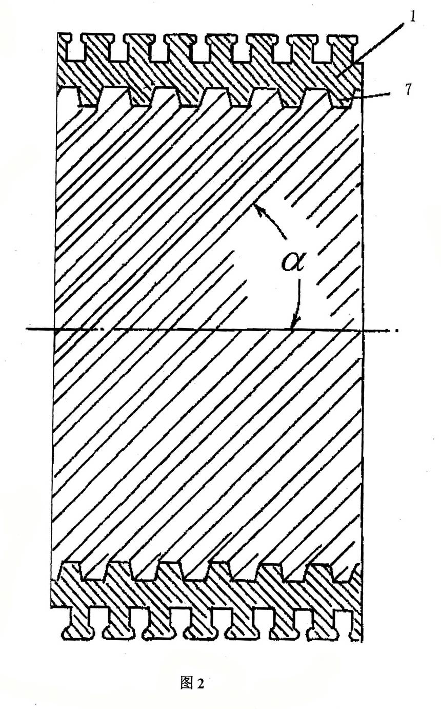
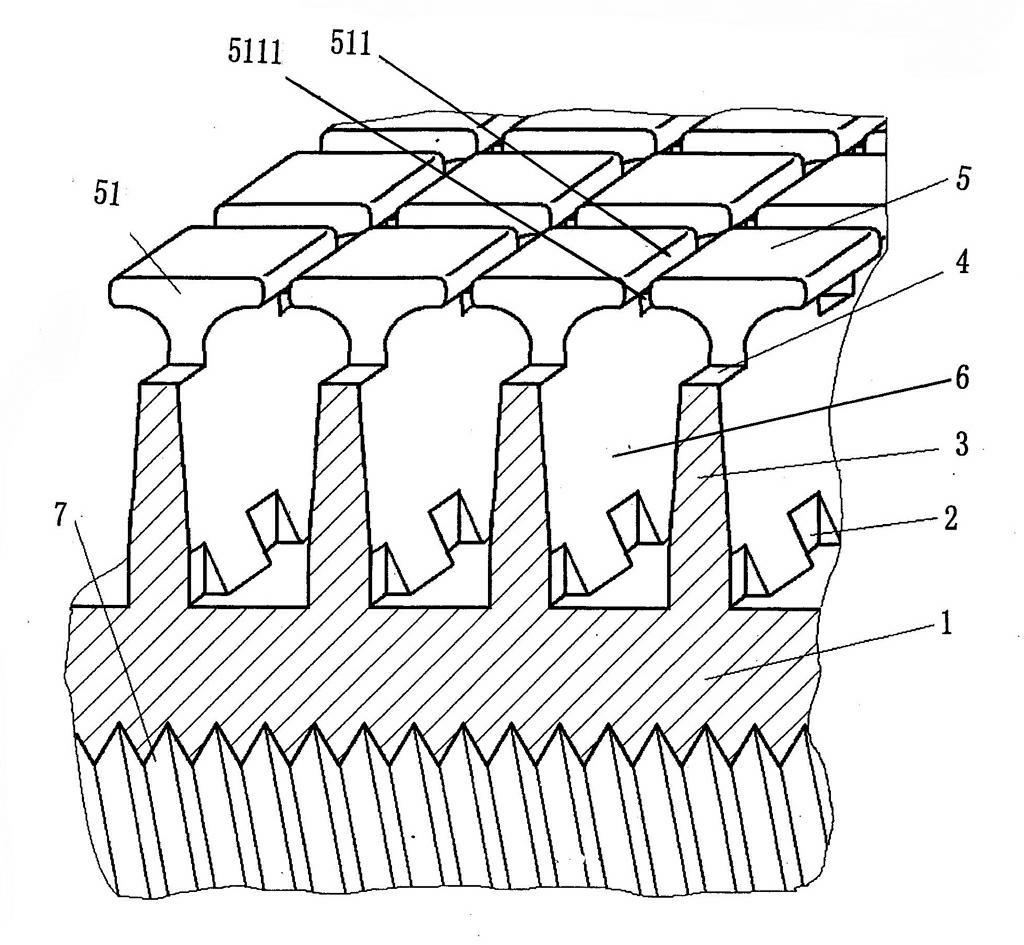
[0024] please see figure 1 and figure 2 The outer fins 3 formed on the outer wall of the tube body 1 according to the present invention can extend around the length direction of the tube body 1 in the form of a helix, or extend around the length direction of the tube body 1 in a ring shape. A plurality of annular outer fins are formed on the outer surface of the tube body 1 , and a plurality of straight fins are formed on the outer surface of the tube body 1 along the axial extension of the tube body 1 . Among them, the tube shape with spiral outer fins is most suitable to be manufactured by adding a tool for cutting the groove 2 with a small-scale cavity structure on the basis of the prior art.

[0025] The outer fin 3 is the basis for forming a cavity structure on the outer surface of the tube body 1. The fin height and fin distance of the outer fin 3 have an appropriate range. If the value is too small, the number of vaporization cores can be greatly increased, but ...

Embodiment 2

[0031] The figure is omitted, and the difference from Embodiment 1 is that a fin stage edge gap 5111 is maintained between the fin stage edge 511 of the T-shaped fin stage 51 on the outer fin top 5 on the adjacent outer fin 3, and the fin stage edge gap 5111 is less than half of the height of the gap between adjacent outer fins 3, for example: when the height of the gap between adjacent outer fins 3 is 2.5 mm, then the edge gap 5111 of the fin platform is less than 1.25 mm. The cavity 6 with the large-scale cavity structure also contains the groove 2 with the small-scale cavity structure inside by the edge gap 5111 of the fin platform. All the other are the same as the description to embodiment 1.


PUM


Abstract

The invention relates to a heat exchanger tube used for an evaporator, belonging to the technical field of heat exchange parts. The heat exchanger tube comprises a tube body and an external fin formed on the external wall surface of the tube body, wherein at least one side of the root of the external fin is provided with grooves which are used for retaining residue steam and is of small-scale hollow cavity structures at intervals. The heat exchanger tube provided by the invention has the advantages that the grooves with small-scale hollow cavity structures are formed on the side surface of at least one side of the root of the external fin at intervals, thus the grooves with small-scale hollow cavity structures are provided for a chamber with a large-scale hollow cavity structure in the existing technology so as to retain the residue steam which is used as the gasifying center for generating the next bubble, thereby improving the activity of the chamber with the large-scale hollow cavity structure and obviously improving the boiling heat transfer coefficient; and the weight of the tube body is reduced because the grooves with the small-scale hollow cavity structures are designed, which is in favor of saving materials and dose not cause the reduction of the strength of the tube body.

Description

technical field [0001] The invention belongs to the technical field of heat exchange components, in particular to a heat exchange tube for an evaporator, which is used to enhance the boiling heat exchange on the outer surface of the heat exchange tube, and is especially suitable for boiling the liquid immersed in the outer surface of the tube Vaporization, or vaporization of a liquid flowing over the outer surface of a tube. Background technique [0002] In many fields such as refrigeration, air conditioning, process engineering, petrochemical industry, energy and power engineering, etc., the boiling and evaporation of liquid on the outer surface of the tube bundle are involved. Especially for evaporators used in refrigeration and air conditioning systems, the boiling heat transfer resistance of the refrigerant when boiling outside the tube is equivalent to or even greater than the forced convection heat transfer thermal resistance inside the tube. Boiling heat transfer can...

Claims


Application Information

Patent Timeline
Patent Type & Authority Applications(China)
IPC IPC(8): F28F1/42F28F13/00
Inventor 陆明华张春明时明华周浩平罗行
Owner JIANGSU CUILONG PRECISION COPPER TUBE CORP
Why Eureka
Try Eureka