
Imaging device and control method for same

A technology for imaging devices and imaging components, applied in projection devices, printing devices, exposure control, etc., can solve the problems of long time required for shooting, deterioration, and large consumption of storage capacity, etc., and achieve the effect of suppressing the degradation of restored image quality

Inactive Publication Date: 2012-01-04
PANASONIC CORP
View PDF9 Cites 7 Cited by
  • Summary
  • Abstract
  • Description
  • Claims
  • Application Information

AI Technical Summary

Problems solved by technology

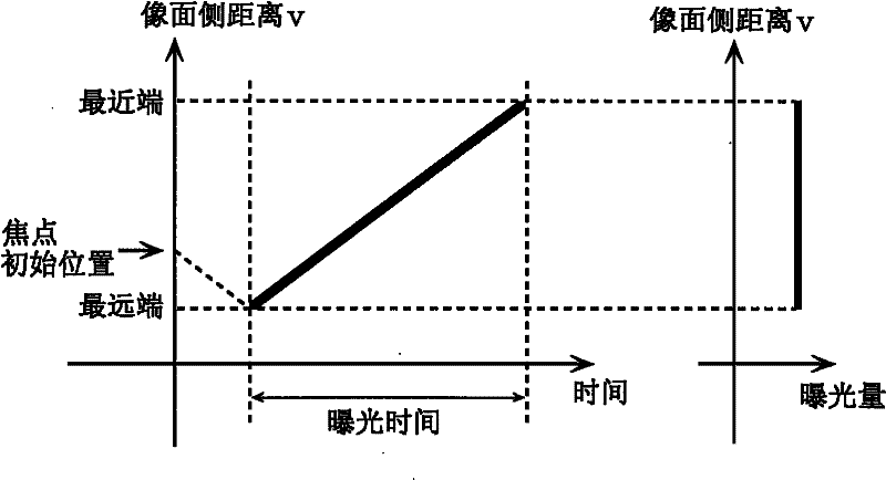
In the case of this method, since a plurality of images need to be taken, there are problems in that the time required for taking pictures is long and the memory consumption is large.
therefore, Image 6 The conventional shifting method shown also has the problem that the image quality of the object position restored at the farthest end and the closest end is degraded compared with the image quality restored at the center thereof.

Method used


Image

  • Imaging device and control method for same
  • Imaging device and control method for same
  • Imaging device and control method for same

Examples


Embodiment 1

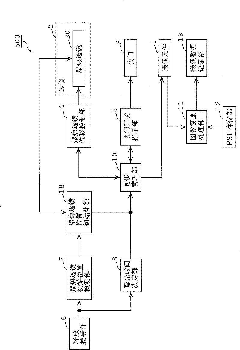
[0093] In the imaging device according to Embodiment 1 of the present invention, in the F-DOF method, the displacement speed of the image plane side distance is decelerated or accelerated at the end of the focus range. Accordingly, in the imaging device according to Embodiment 1 of the present invention, it is not necessary to shift the image plane side at an acute angle at the end of the focus range. Furthermore, in the imaging device according to the first embodiment of the present invention, the sharpness of the image at the end of the focus range can be brought closer to the sharpness of the middle region. In this way, in the imaging device according to the first embodiment of the present invention, in F-DOF, it is possible to suppress deterioration of the restored image quality at the farthest end and the closest end.

[0094] refer to Figure 9 to Figure 19 An imaging device in Embodiment 1 of the present invention will be described.

[0095] First, the schematic confi...

Embodiment 2

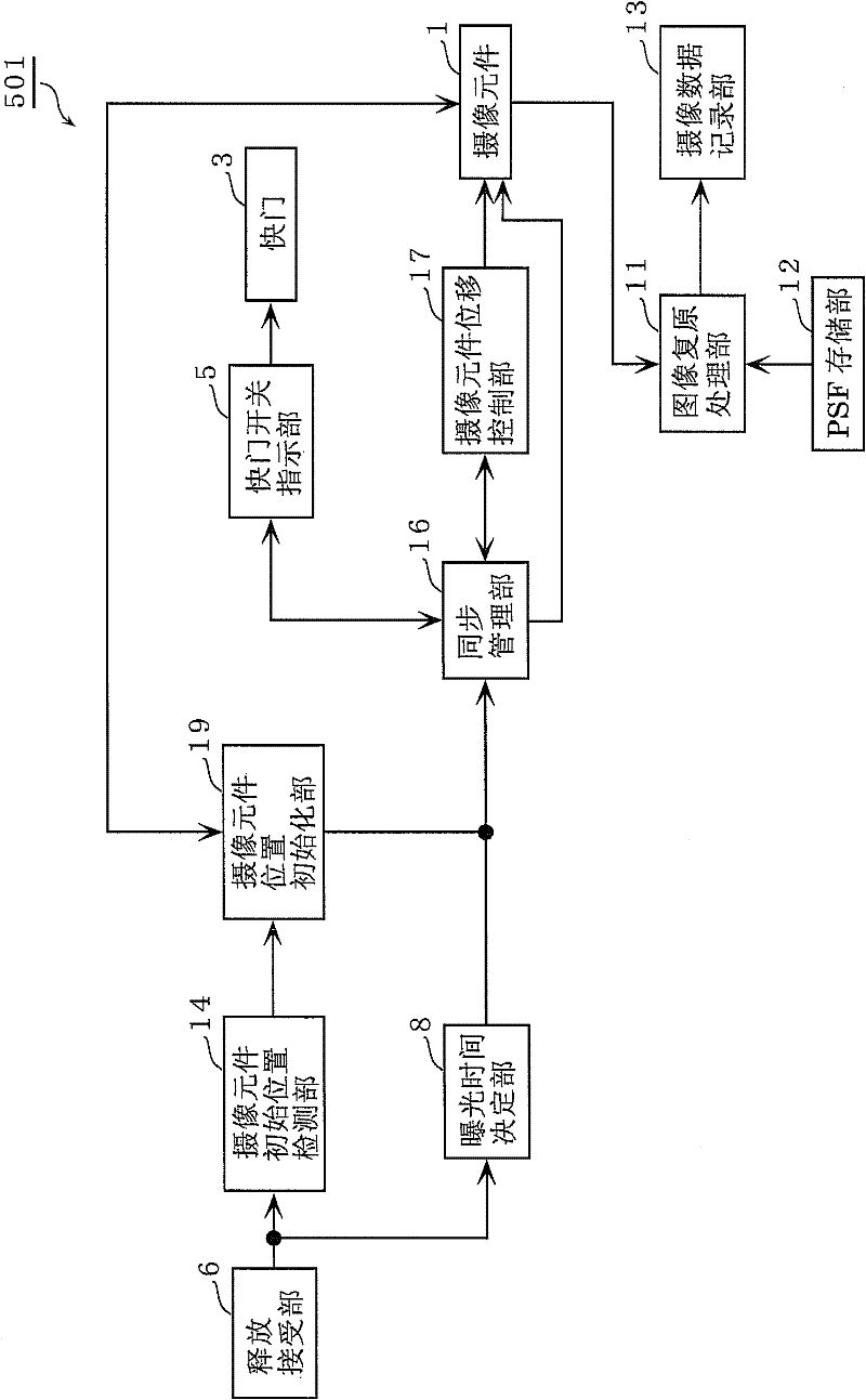
[0156] In Embodiment 2 of the present invention, an example in which the focus position is shifted by moving the position of the imaging element 1 will be described. Furthermore, the schematic configuration of the imaging device 200 according to Embodiment 2 of the present invention is the same as Figure 9 same.

[0157] refer to Figure 20 as well as Figure 21 The imaging device in Embodiment 2 of the present invention will be described.

[0158] Figure 20 It is a block diagram of the imaging device 200 according to the second embodiment of the present invention. The camera device 200, with Figure 10 Compared with the configuration of the imaging device 100 shown, instead of the focus lens initial position detection unit 7, the focus lens position initialization unit 18, the focus lens shift mode determination unit 9, the synchronization management unit 10A, and the focus lens shift control unit 4A, it includes An imaging element initial position detection unit 14 ,...


PUM


Abstract

The disclosed imaging device (100) is provided with a displacement control unit (22) which displaces the focus position of the imaging device (100) on the side towards the subject to be imaged by changing the imaging surface distance, and a displacement pattern setting unit (21) which sets a displacement pattern in a frame period to be implemented by the displacement control unit (22). The displacement pattern setting unit (21) sets the displacement pattern of the focus position so that: during the acceleration period of the frame period, the displacement rate of the imaging surface distance increases from zero; during the constant velocity period, the imaging surface distance is displaced at a constant rate; and during the deceleration period, the displacement rate of the imaging surface distance decreases to zero. The acceleration period and the deceleration period are each at least 1 / 10 of the length of the frame period.

Description

technical field [0001] The present invention relates to an imaging device and a control method thereof, and particularly relates to an imaging device that changes a focus position during exposure. Background technique [0002] In general, the following three methods can be mainly shown as methods for realizing extended depth of field (hereinafter, referred to as EDOF). The first method is to insert an optical element called a phase plate into an optical system to make the blur in the depth direction uniform. Furthermore, in this method, image restoration processing is performed on the obtained image using a previously measured blur pattern or a blur pattern calculated by simulation. According to this method, an EDOF image is generated. This method is called Wavefront Coding (hereinafter referred to as WFC) (see Non-Patent Document 1). [0003] The second method is to measure the distance with high precision for each partial region of the image by devising the shape of the...

Claims


Application Information

Patent Timeline
Patent Type & Authority Applications(China)
IPC IPC(8): H04N5/225G02B7/28G03B3/00G03B7/097H04N5/232
CPCG03B7/097G02B27/0075H04N5/23212G02B7/38G03B13/36H04N23/959
Inventor 河村岳
Owner PANASONIC CORP
Learn More