In-place measurement method and device for gas
A measurement method and a technology of a measurement device, which are applied in the direction of measurement devices, color/spectral characteristic measurement, and testing moving fluid/granular solids, etc., can solve problems such as large impact, increased measurement cost, and low measurement accuracy of gas sensors, and achieve Low cost, cost reduction, and high measurement accuracy
- Summary
- Abstract
- Description
- Claims
- Application Information
AI Technical Summary
Problems solved by technology
Method used
Image
Examples
Embodiment 1
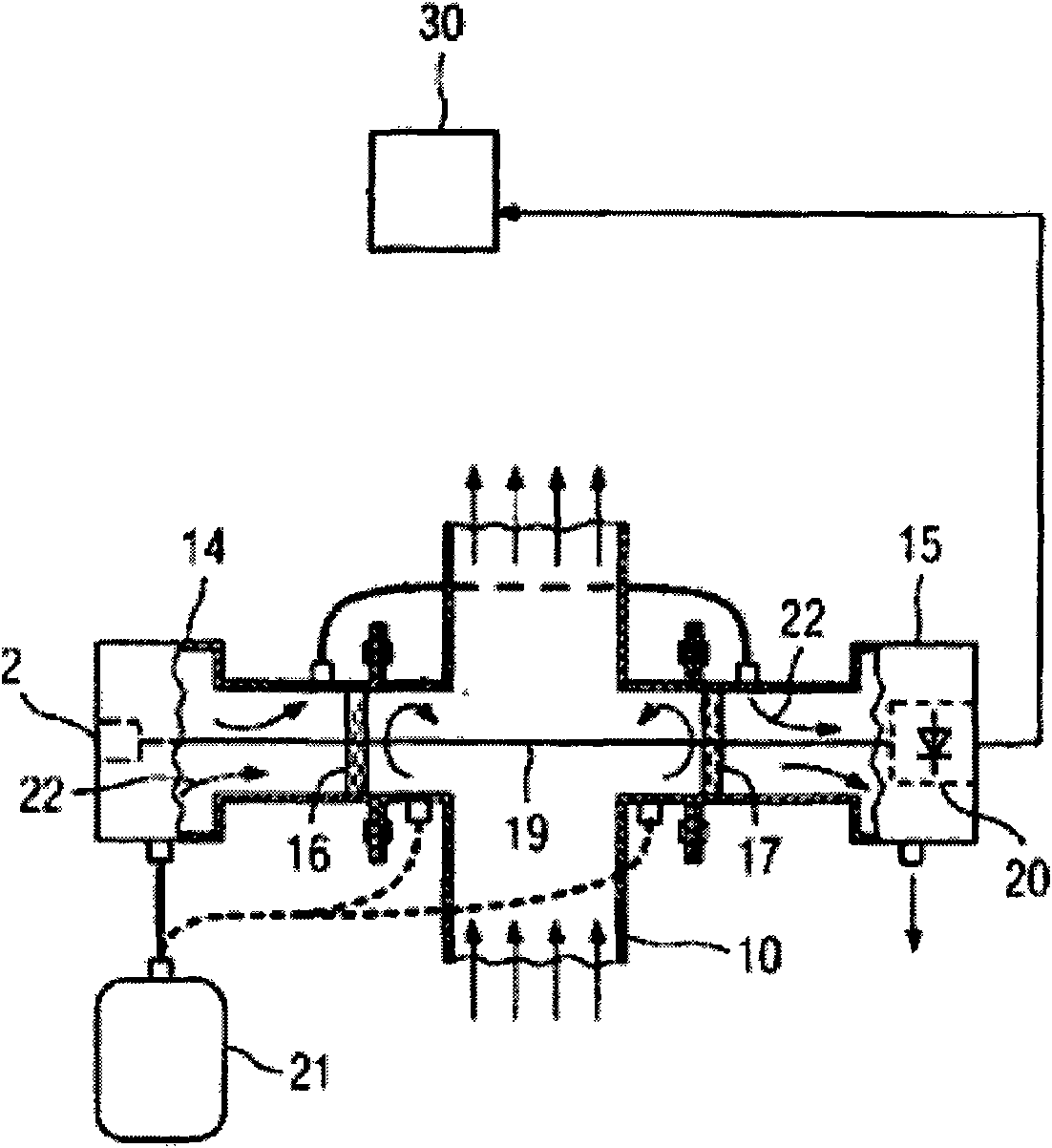
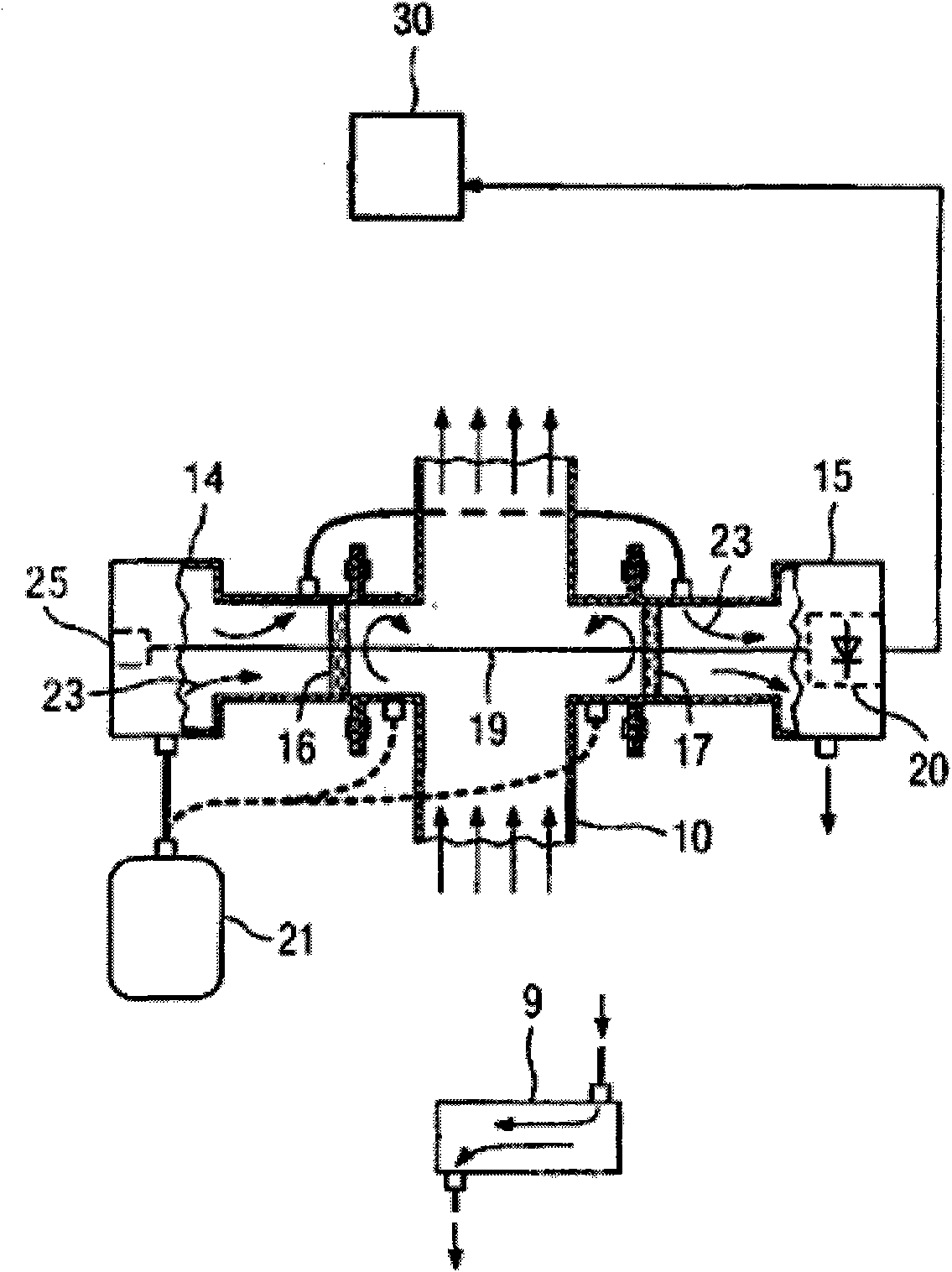
[0056] Such as figure 2 As shown, an in-situ measuring device for oxygen in an incinerator, the temperature in the incinerator is about 1223K, and the measuring device includes:
[0057] The light emitting unit 14 includes a laser 25 and a driving module, the output light frequency of the laser 25 includes a frequency v corresponding to the absorption line I of oxygen 1 =13164.18cm -1 , corresponding to the frequency v of the absorption line II of oxygen 2 =13163.78cm -1 . When the driving module works, the frequency of the output light of the laser 25 can sweep the above frequency. Such as Figure 4 As shown, under unit concentration and unit light path, at the absorption line I of oxygen, the absorption at high temperature (1223K) is much higher than the absorption at normal temperature (300K), more than 15 times.
[0058] The light receiving unit 15 includes a detector 20, and the selection of the detector 20 is a prior art in the field, and details are not repeated ...
Embodiment 2
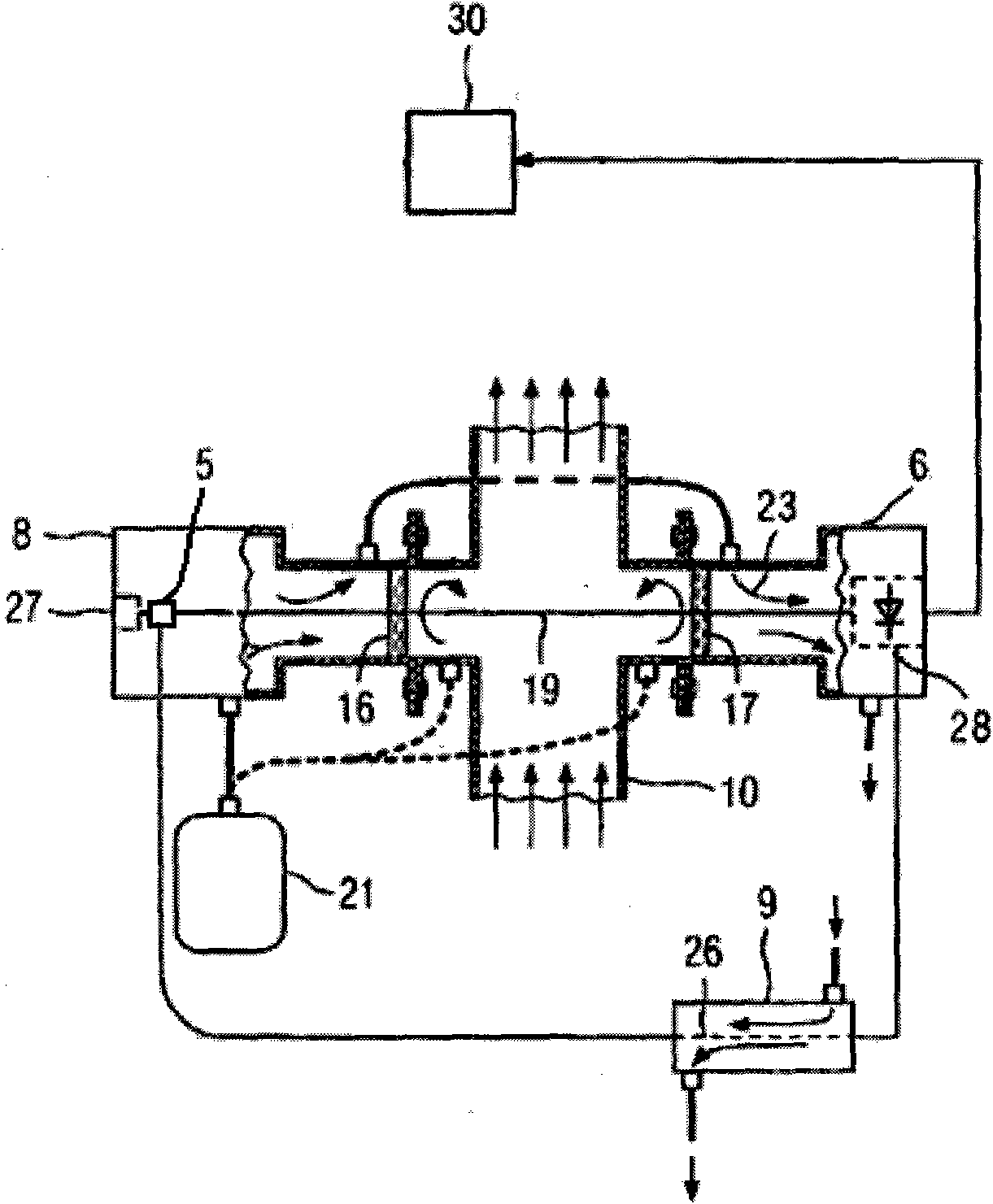
[0081] Such as image 3 As shown, an in-situ measuring device for oxygen in an incinerator, the temperature in the incinerator is about 1223K, and the measuring device includes:
[0082] The light emitting unit 8 includes a laser 27, a driving module, and an optical splitter 5, and the output light frequency of the laser 27 includes a frequency v corresponding to the absorption line I of oxygen 1 =13164.93cm-1 , corresponding to the frequency v of the absorption line II of oxygen 2 =13164.69cm -1 . When the driving module works, the output light frequency of the laser 27 can sweep the above frequency. Such as Figure 5 As shown, under unit concentration and unit light path, at the absorption line I of oxygen, the absorption at high temperature (1223K) is much higher than the absorption at normal temperature (300K), more than 8 times.
[0083] The light-receiving unit 6 includes a detector 28, and the selection of the detector 28 is a prior art in the field, and details ar...
Embodiment 3
[0107] A kind of in-situ measuring device of oxygen in the incinerator, different from embodiment 2 is:
[0108] 1. Instead of installing an optical splitter, set the first optical switch in the measurement optical path (the optical path formed between the laser and the detector by the measuring light), and set the first optical switch in the calibration optical path (the calibration light is formed between the laser and the detector) The second optical switch is set in the optical path).
[0109] When in the measuring state, the first optical switch is turned on and the second optical switch is turned off; when in the calibration state, the first optical switch is turned off and the second optical switch is turned on.
[0110] 2. The total optical path of the measuring light in the purging gas is 0.3m, and the oxygen content in the purging air is 21%; the measuring optical path in the combustion furnace is 3m, and the oxygen content is about 10%; In the process, at the absor...
PUM
 Abstract
Description
Claims
Application Information
 - R&D
- Intellectual Property
- Life Sciences
- Materials
- Tech Scout
- Unparalleled Data Quality
- Higher Quality Content
- 60% Fewer Hallucinations
Browse by: Latest US Patents, China's latest patents, Technical Efficacy Thesaurus, Application Domain, Technology Topic, Popular Technical Reports.
© 2025 PatSnap. All rights reserved.Legal|Privacy policy|Modern Slavery Act Transparency Statement|Sitemap|About US| Contact US: help@patsnap.com


