Single-mode optical fiber and optical system

A single-mode fiber, fiber core technology, applied in optics, transmission systems, cladding fibers, etc., can solve the problem of increasing manufacturing costs, failing to provide satisfactory distribution characteristics and/or propagation characteristics, and increasing fiber manufacturing costs. Macrobending loss and other problems, to achieve the effect of low bending loss

Active Publication Date: 2012-01-11
DRAKA COMTEQ BV
View PDF12 Cites 20 Cited by
  • Summary
  • Abstract
  • Description
  • Claims
  • Application Information

AI Technical Summary

Problems solved by technology

[0020] Therefore, the question that arises is: how to increase the effective area Aeff to more than 150 μm 2 , without substantially increasing manufacturing costs and without compromising performance in terms of bend loss
[0040] Thus, the prior art d

Method used


Image

  • Single-mode optical fiber and optical system
  • Single-mode optical fiber and optical system
  • Single-mode optical fiber and optical system

Examples


Embodiment Construction

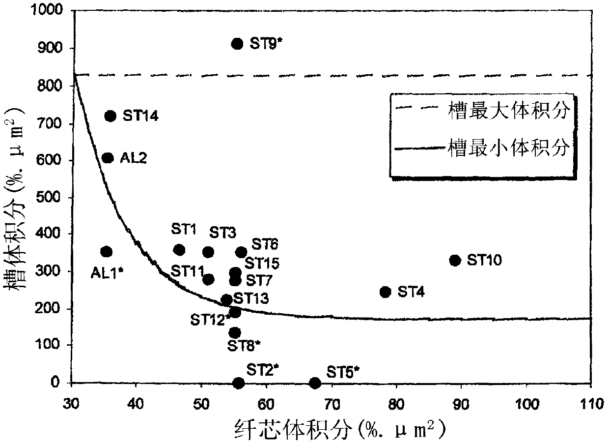
[0077] The present invention proposes to increase the effective area Aeff of the single-mode optical fiber to more than 150 μm by relaxing the constraints on the cut-off wavelength λcc in the optical cable, that is, by allowing λcc to exceed 1450 nm 2 .

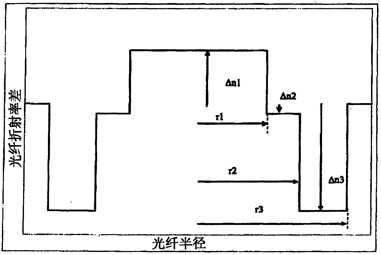
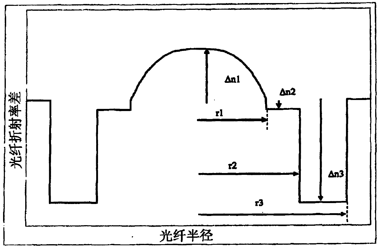
[0078] To this end, the invention proposes the use of fiber distributions with buried cladding.

[0079] Thus, the optical fiber of the present invention has a central core, an intermediate cladding, and a buried cladding or trench. The central core, intermediate cladding and buried cladding are typically produced by chemical vapor deposition (CVD) inside a silica tube. The outer optical cladding consists of a silica tube and the outer cladding of the silica tube, usually made of natural or doped silica, but any other deposition technique (vapor axial deposition (VAD) , vapor axial deposition) or external vapor deposition (OVD, outside vapor deposition)) to produce the outer optical cladding.

[0080] For example, Plasma C...


PUM

PropertyMeasurementUnit
Areaaaaaaaaaaa
Radiusaaaaaaaaaa
Wavelengthaaaaaaaaaa

Abstract

The invention relates to a single-mode optical fiber and an optical system, the single-mode optical fiber comprises a central core, an intermediate cladding, a trench, and optical cladding. The central core has a refractive index difference n 1 relative to the optical cladding in the range 2.610 -3 to 3.510 -3 . The trench has a radius r 3 that is less than 24 [mu]m. The refractive index difference n 3 of the trench relative to the optical cladding is in the range -15.010 -3 to -4.510 -3 at 633 nm. The volume V 13 of the trench, defined as follows: V 13 is in the range 170 %.[mu]m 2 to 830 %.[mu]m 2 . This fiber has an effective area greater than or equal to 150 [mu]m 2 at a wavelength of 1550 nm and lower bending losses. Use in particular in long-haul terrestrial systems or undersea systems with or without repeaters.

Description

technical field [0001] The invention relates to the field of optical fiber transmission, more specifically, to an optical fiber with increased effective area but no increased bending loss and a corresponding optical system. Background technique [0002] Generally speaking, in the field of optical fibers, the concept of effective area is introduced in order to calculate nonlinear effects. The effective area generally corresponds to the usable section of a fiber defined based on the distribution of modes propagated in the fiber's field. [0003] By way of non-limiting example, the effective area Aeff is defined as follows: [0004] Aeff = 2 π ( ∫ 0 ∞ | F ( r ) ...

Claims


Application Information

Patent Timeline
IPC IPC(8): G02B6/02G02B6/036H04B10/18
CPCG02B6/0281G02B6/02019G02B6/0365
Inventor M·比戈-阿斯楚克P·斯拉德S·理查德
Owner DRAKA COMTEQ BV
Why Eureka
Try Eureka