Gate drive thyristor circuit and electrostatic protection circuit

An electrostatic protection and thyristor technology, which is applied in the field of integrated circuit electrostatic protection circuit design, can solve problems such as the inability to meet the needs of long pulse width ESD electrostatic pulse discharge, achieve strong electrostatic discharge capability, and promote the effect of triggering conduction.

Active Publication Date: 2015-10-21
SHANGHAI HUAHONG GRACE SEMICON MFG CORP
View PDF3 Cites 0 Cited by
  • Summary
  • Abstract
  • Description
  • Claims
  • Application Information

AI Technical Summary

Problems solved by technology

Solve the problem that the existing gate drive thyristor circuit using RC coupling loop cannot meet the demand of long pulse width ESD electrostatic pulse discharge

Method used


Image

  • Gate drive thyristor circuit and electrostatic protection circuit
  • Gate drive thyristor circuit and electrostatic protection circuit
  • Gate drive thyristor circuit and electrostatic protection circuit

Examples


Embodiment Construction

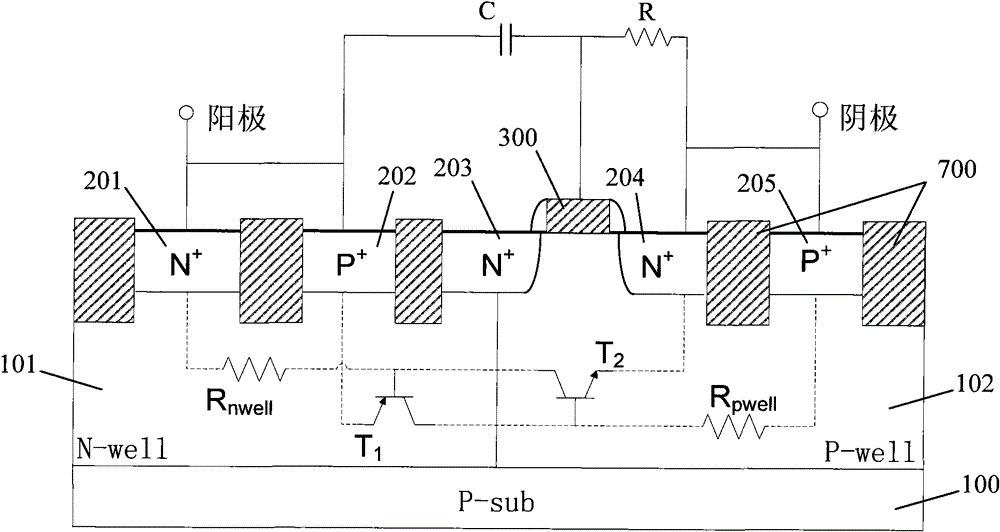
[0040] The existing gate-driven thyristor circuit utilizes the coupling effect of the RC coupling loop to couple the potential of the anode to the control grid to achieve the purpose of reducing the trigger voltage of the thyristor. However, since the coupling effect is not continuous, the potential on the control grid will quickly hysteresis for a long-pulse ESD pulse, and the effect of reducing the trigger voltage of the thyristor is limited. Therefore, it does not meet the requirement of long-term electrostatic discharge. In the gate-driven thyristor circuit provided by the present invention, a forwardly connected diode path is formed between the base (N well) of the parasitic PNP transistor in the PMOS transistor and the control grid, and between the control grid and the cathode (the said between two poles) Connecting diodes in the forward direction refers to connecting the positive end of the diode to the previous pole, and the negative end to the next pole, which is here...


PUM


Abstract

The invention provides a gate driving thyristor circuit and an electrostatic protection circuit. The gate driving thyristor circuit comprises a semiconductor substrate, and an N pit and a P pit which are adjacent and positioned in the semiconductor substrate, a first N+-type injection region positioned in the N pit, a second N+-type injection region positioned in the P pit, a P-channel metal oxide semiconductor (PMOS) transistor positioned on the N pit, an anode, a cathode and a gate driving circuit; the PMOS transistor comprises a control gate on the surface of the N pit, and a P+-type source region and a P+-type drain region which are positioned in the N pit on the two sides of the control gate; the drain region extends into the P pit, and is connected with the P pit and isolated from the second N+-type injection region; the source region is isolated from the first N+-type injection region; the anode is electrically connected with the first N+-type injection region and the source region respectively; the cathode is electrically connected with the P pit and the second N+-type injection region respectively; and the gate driving circuit comprises diodes which are positively connected between the N pit and the control gate and between the control gate and the cathode respectively. The gate driving thyristor circuit is capable of continuously reducing the trigger voltage of the thyristor.

Description

technical field [0001] The invention relates to the design field of integrated circuit electrostatic protection circuits, in particular to a gate driving thyristor circuit and an electrostatic protection circuit. Background technique [0002] Nowadays, with the improvement of integrated circuit manufacturing process, the feature size of CMOS integrated circuits is getting smaller and smaller. However, subsequently, the protection ability of integrated circuits against electrostatic discharge (ESD, Electrostatic Discharge) is getting weaker and weaker, that is, as the size of devices becomes smaller and smaller, the electrostatic voltage that devices can withstand is also getting smaller and smaller. Small. Moreover, since the static electricity in the working environment of the integrated circuit will not change due to the reduction of the size of the integrated circuit, compared with the large-scale integrated circuit, the integrated circuit manufactured by the deep submic...

Claims


Application Information

Patent Timeline
Patent Type & Authority Patents(China)
IPC IPC(8): H01L27/02H01L27/06H02H9/00
Inventor 单毅陈晓杰
Owner SHANGHAI HUAHONG GRACE SEMICON MFG CORP
Why Eureka
Try Eureka