Liquid crystal display device

A liquid crystal display device, liquid crystal technology, applied in instruments, nonlinear optics, optics, etc., can solve the problems of rising cost and inferior viewing angle characteristics, and achieve low gray level characteristics, good wide viewing angle characteristics, and good high-speed response. sexual effect

Active Publication Date: 2012-01-11
SHARP KK
View PDF9 Cites 2 Cited by
  • Summary
  • Abstract
  • Description
  • Claims
  • Application Information

AI Technical Summary

Problems solved by technology

[0009] However, although the OCB mode exhibits high-speed responsiveness, it requires an operation to transition from the display orientation as the initial orientation to the bend orientation during driving when the power is turned on, and a drive circuit for initial transition is required in addition to the normal drive circuit. Therefore, There is a problem of rising costs
In addition, there is room for further improvement in terms of viewing angle characteristics compared to MVA mode, IPS mode, etc.

Method used


Image

  • Liquid crystal display device
  • Liquid crystal display device
  • Liquid crystal display device

Examples


Embodiment approach 1

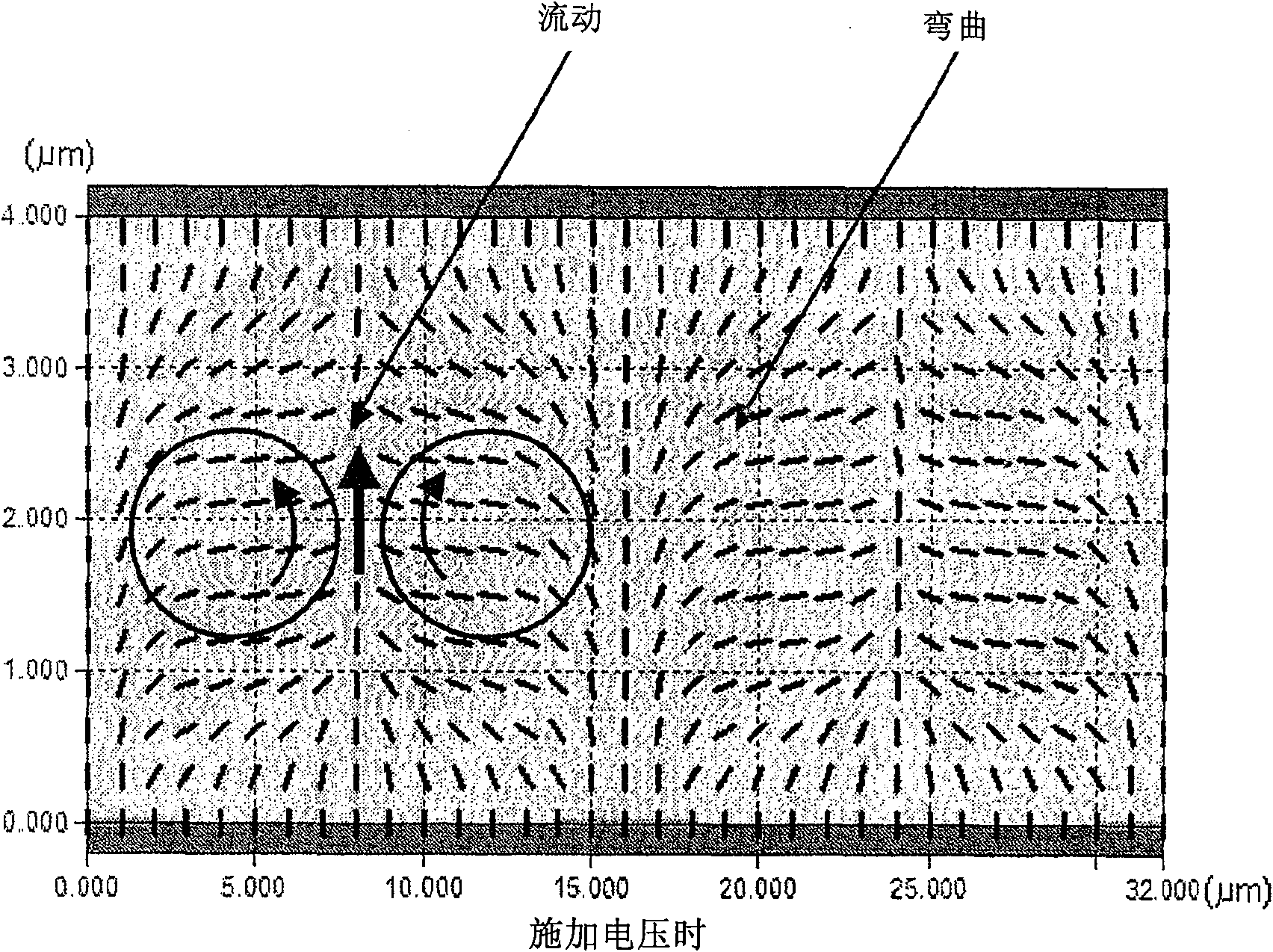
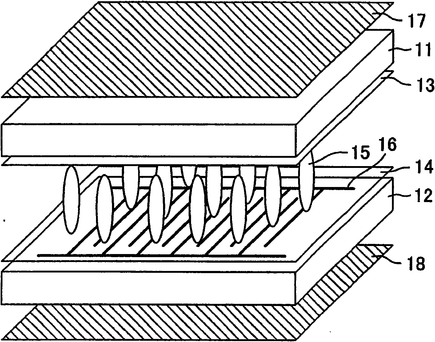
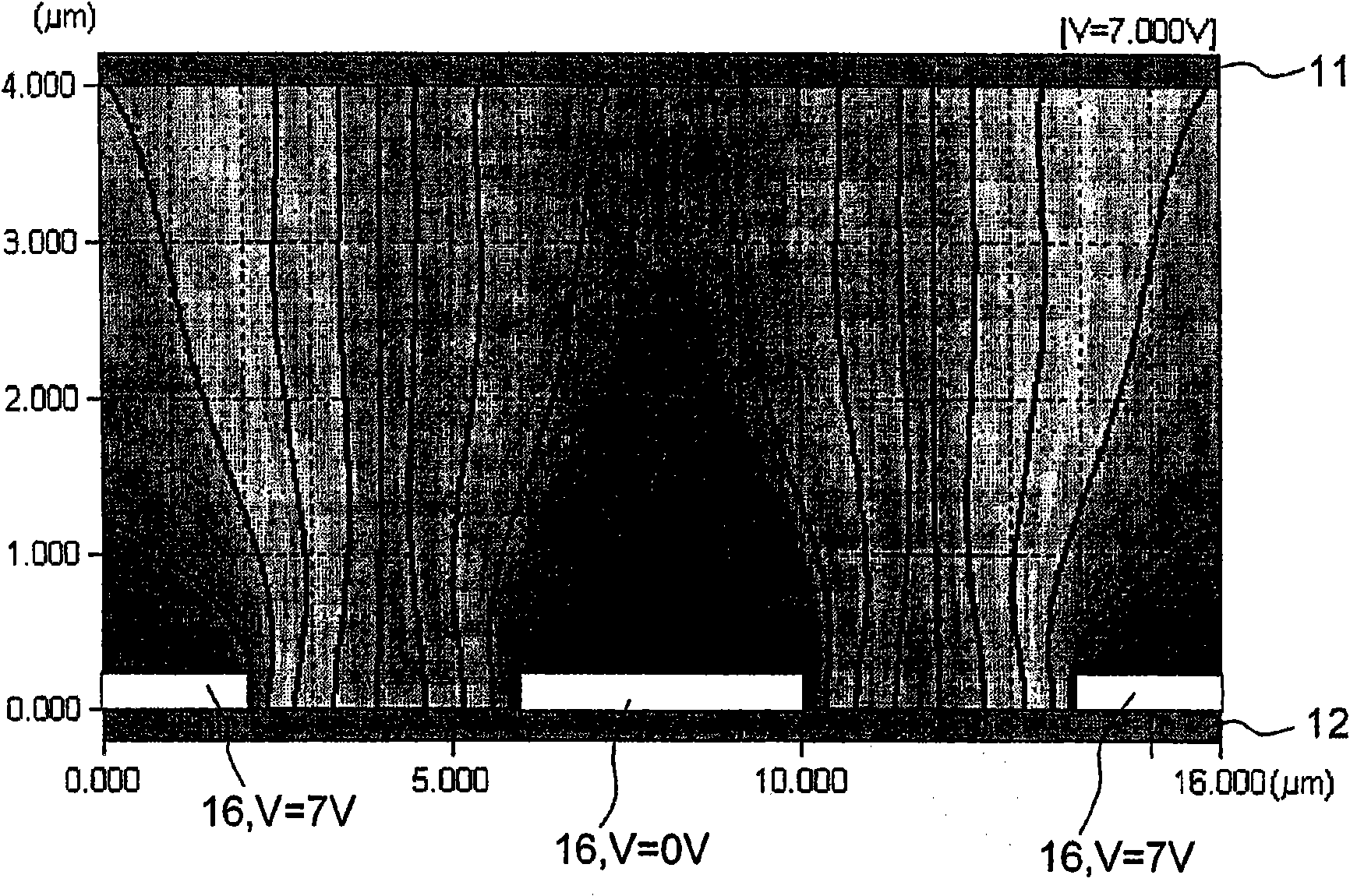
[0091] The liquid crystal display device of the present embodiment is a liquid crystal display device in which an electric field intensity distribution is formed in a cell by applying an electric field, thereby realizing bend alignment of liquid crystals. In addition, the liquid crystal display device of this embodiment is a liquid crystal display device in which an electric field is applied to p-type nematic liquid crystals (nematic liquid crystals having positive dielectric anisotropy) aligned vertically in the lateral direction with respect to the substrate surface, and is characterized in that In that a more curved arrangement is formed by applying an electric field. figure 1 It is a schematic perspective view showing the basic configuration of the liquid crystal display device of the first embodiment. Vertical alignment films 13, 14 are arranged on the two transparent substrates 11, 12, and p-type nematic liquid crystals (liquid crystal molecules 15) exhibit vertical ali...

Embodiment 1

[0103] A schematic cross-sectional view showing the basic structure of the liquid crystal display element of Example 1 is at Figure 4 Indicated. A plurality of liquid crystal display elements having various electrode widths L and electrode intervals S were produced. First, the alignment film JALS- 204 (5 wt.%, γ-butyrolactone solution), and fired at 200° C. for two hours to form an alignment film 44 . The film thickness of the alignment film 44 at this time was 60 nm. Similarly, an alignment film 45 having a film thickness of 60 nm was formed on the glass substrate 43 using the same alignment film paint as that of the alignment film 44 . Thereafter, resin beads 46 (Micropearl SP: microbead SP) manufactured by Sekisui Chemical Co., Ltd. with a diameter of 4 μm were dispersed on the substrate 42, and sealing resin 47 (Stract bond) manufactured by Mitsui Topress Chemical Co., Ltd. was printed on the substrate 43. XN-21-S: Structural body adhesive XN-21-S), these board|substr...

Embodiment 2

[0124] The basic structure and Figure 4 Similarly, a liquid crystal cell in which the electrode width L is 4 μm, the electrode spacing S is 4 μm, and the cell gap is 4 μm.

[0125] First, a glass substrate 42 having a comb-shaped electrode (comb-teeth electrode) 41 made of ITO is dipped in the chemical formula CF 3 -(CF 2 ) 17 -SiCl 3 After 5 minutes in the 0.01mol / l chloroform-NMP mixed solution (chloroform: NMP mixing ratio (volume ratio) = 1:10) of the indicated silane coupling agent, dry it at 120°C in dry nitrogen. After drying for 1 hour, an alignment film 44 (interfacial anchor energy: 5×10 -5 J / m 2 ).

[0126] Similarly, an alignment film 45 was formed on the glass substrate 43 using the same alignment film material as that of the alignment film 44 . Thereafter, resin beads 46 (Micropearl SP) with a diameter of 4 μm produced by Sekisui Chemical Co., Ltd. were dispersed on the substrate 42, and sealing resin 47 (Structure Adhesive XN -21-S) These substrates wer...


PUM

PropertyMeasurementUnit
widthaaaaaaaaaa
widthaaaaaaaaaa
thicknessaaaaaaaaaa

Abstract

Provided is a liquid crystal display device which can simultaneously realize an excellent wide view angle characteristic and a high-speed response and can perform display by a display method not requiring an initial bend shifting operation. The liquid crystal display device contains p-type nematic liquid crystal sandwiched by two substrates, at least one of which is transparent. When no voltage is applied, the p-type nematic liquid crystal is orientated to be vertical against the two substrate planes. At least one of the two substrates has a comb-shaped electrode. The liquid crystal display device may have an aspect that the electrode width L of the comb-shaped electrode and the electrode interval S satisfy the relationship: (S + 1.7) / (S + L) >= 0.7. Moreover, the liquid crystal display device may have an aspect that one pixel region as a first area and a second area having the ratio S / L (L is the electrode width of the comb-shaped electrode and S is the electrode interval) different from that of the first area. These aspects may be used in combination.

Description

technical field [0001] The present invention relates to a liquid crystal display device. More specifically, it relates to a liquid crystal display device suitable for a display method in which transmission of light is controlled by bending and deforming a liquid crystal layer by applying a voltage. Background technique [0002] Liquid crystal display devices are characterized by thinness, light weight, and low power consumption, and are widely used in various fields. Also, its display performance has been exceptionally advanced with the passage of time, and has now been developed to surpass the CRT (cathode ray tube). [0003] The display method of a liquid crystal display device is determined by how liquid crystals are arranged in a cell. Conventionally, as display methods of liquid crystal display devices, for example, TN (Twisted Nematic: twisted nematic) mode, MVA (Multi-domain Vertical Alignment: multi-domain vertical alignment) mode, and IPS (In-plane Switching: in-p...

Claims


Application Information

Patent Timeline
Patent Type & Authority Applications(China)
IPC IPC(8): G02F1/1343G02F1/139
CPCG02F1/134363G02F1/133707G02F2001/134381G02F2201/124G02F1/134381
Inventor 石原将市神崎修一樱井猛久村田充弘
Owner SHARP KK
Why Eureka
Try Eureka