
Method for exhaust gas purification

A technology for waste gas purification and waste gas, which is applied in chemical instruments and methods, separation methods, and dispersed particle separation. Uniform, long-lasting effect

Inactive Publication Date: 2012-01-18
JIANGXI JDL ENVIRONMENTAL PROTECTION CO LTD
View PDF4 Cites 15 Cited by
  • Summary
  • Abstract
  • Description
  • Claims
  • Application Information

AI Technical Summary

Problems solved by technology

[0003] 1) In the spray absorption tower, the flow from bottom to top is the mixed gas of exhaust gas and air, which reduces the effective contact time between exhaust gas and the absorption liquid sprayed down, and the bubbles are large and the transfer speed is slow, so that the exhaust gas cannot get Fully absorbed, difficult to meet emission standards
[0004] 2) The absorption liquid is sprayed down along the filler, and the liquid droplets are often large due to easy clogging, and the distribution of liquid is not uniform, which may easily cause short flow of exhaust gas and poor absorption effect
[0005] 3) The exhaust gas and liquid mist on the top of the spray absorption structure are large, the visual effect is poor, and it will also cause secondary pollution
[0006] 4) The amount of absorption liquid used in the spray absorption method is large, the absorption tower is high, the energy consumption of the circulating pump is high, the saturation concentration of the absorption liquid is low, and the operating cost is high

Method used


Image

  • Method for exhaust gas purification
  • Method for exhaust gas purification
  • Method for exhaust gas purification

Examples


Embodiment 1

[0022] A new type of exhaust gas purification method has the following steps in sequence:

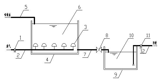
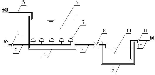
[0023] 1) The carbon dioxide waste gas is transported from the fan 1 through the waste gas pipe 2 to the diffusion plate microporous aeration device 3 at the bottom of the absorption tank 4, and enters the absorption tank 4 after being fully diffused;

[0024] 2) The absorption tank 4 is filled with monoethanolamine absorbing liquid matched with carbon dioxide waste gas, the concentration of which is 10%-30%, and the carbon dioxide waste gas passes through the microporous aeration head 3 of the diffusion plate microporous aeration device to form tiny bubbles into the monoethanolamine The absorption liquid 6, the carbon dioxide waste gas diffuses step by step from the bottom of the monoethanolamine absorption liquid 6 to the upper part, and is fully absorbed in the relatively static monoethanolamine absorption liquid 6. The monoethanolamine absorption solution 6 is placed in the absorption ta...

Embodiment 2

[0027] A new type of exhaust gas purification method has the following steps in sequence:

[0028] 1) The sulfur dioxide waste gas is transported from the fan 1 through the waste gas pipe 2 to the diffusion tube microporous aeration device 3 provided at the bottom of the absorption tank 4, and enters the absorption tank 4 after being fully diffused;

[0029] 2) The absorption tank 4 is filled with lime water absorption liquid that matches the sulfur dioxide waste gas, and its concentration is 5%-15%. The sulfur dioxide waste gas passes through the diffuser tube, microporous aeration device, and the microporous aeration head 3 to form tiny bubbles into the lime water. The absorption liquid 6, the sulfur dioxide waste gas diffuses step by step from the bottom of the lime water absorption liquid 6 to the upper part, and is fully absorbed in the relatively static lime water absorption liquid 6. The lime water absorption liquid 6 is placed in the absorption tank 4. After the sulfur diox...

Embodiment 3

[0032] A new type of exhaust gas purification method has the following steps in sequence:

[0033] 1) The ammonia waste gas is transported from the fan 1 through the waste gas pipe 2 to the membrane-type microporous gas diffuser 3 at the bottom of the absorption tank 4, and enters the absorption tank 4 after being fully diffused;

[0034] 2) The absorption tank 4 is filled with sulfuric acid absorption liquid matched with the ammonia waste gas, the concentration of which is 20%-30%. The ammonia waste gas passes through the membrane type microporous gas diffuser microporous aeration head 3 and then forms tiny bubbles into it Sulfuric acid absorption liquid 6, the ammonia waste gas diffuses step by step from the bottom of the sulfuric acid absorption liquid 6 to the upper part, and is fully absorbed in the relatively static sulfuric acid absorption liquid 6. The sulfuric acid absorption liquid 6 is placed in the absorption tank 4, and the ammonia waste gas is absorbed After the micro...


PUM


Abstract

The invention discloses a novel method for exhaust gas purification. The method comprises the following steps that 1) exhaust gas is fed into a microporous aerator 3 arranged at the bottom of an absorption cell 4 by a fan 1, is adequately diffused and then is fed to the absorption cell 4; 2) an absorption solution 6 matched with the exhaust gas is filled into the absorption cell 4; the exhaust gas passes through the microporous aerator 3, then forms tiny bubbles and enters the absorption solution 6; and the exhaust gas is diffused gradually in the absorption solution 6 from bottom to top to be absorbed fully in the absorption liquid 6 which is static relatively. The novel method for exhaust gas purification can absorb and treat exhaust gas efficiently and thoroughly, has high saturated concentration of an absorption solution and high recycle values, and overcomes the defects of high structure adopted by the existing spray absorption method, high energy consumption, low efficiency and incomplete absorption.

Description

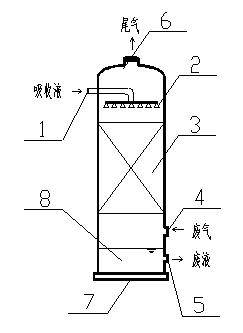
Technical field [0001] The invention relates to an exhaust gas purification treatment method, in particular to an exhaust gas absorption treatment method. Background technique [0002] The existing absorption tower spray absorption method, such as figure 2 As shown, the absorption liquid is sprayed from the upper absorption liquid inlet 1 of the absorption tower 7 through the nozzle 2 into the absorption tower 7 and the absorption liquid flows through the packing 3 from top to bottom. The exhaust gas enters the absorption tower 7 from the exhaust gas inlet 4 at the lower part of the absorption tower 7, flows through the packing 3 from bottom to top, and contacts with the spray absorption liquid dripping from the top to the packing 3 in the reverse flow phase and is absorbed. The absorbed gas escapes from the tail gas outlet 6 at the top of the absorption tower 7. The waste liquid 8 after absorbing the exhaust gas is discharged from the absorption liquid waste liquid outlet 5 at ...

Claims


Application Information

Patent Timeline
Patent Type & Authority Applications(China)
IPC IPC(8): B01D53/14
Inventor 廖志民
Owner JIANGXI JDL ENVIRONMENTAL PROTECTION CO LTD
Learn More