
High-energy mixer for well cementation in oil and gas fields

A technology for oil and gas fields and mixers, which is used in wellbore/well components, earthmoving, sealing/packaging, etc. Pulp effect, improve wear resistance, reduce labor intensity

Inactive Publication Date: 2012-01-18
SHANDONG VICTOR OILFIELD EQUIP
View PDF5 Cites 3 Cited by
  • Summary
  • Abstract
  • Description
  • Claims
  • Application Information

AI Technical Summary

Problems solved by technology

[0002] The high-energy mixer is the key component of the oilfield cementing vehicle for the initial mixing of cement ash and clean water. The high-energy mixers currently used generally have complex structures, easy blockage, low mixing efficiency, high labor intensity, and short service life. The reasons are as follows:
[0003] 1. The secondary ash mixing pipe adopts the bull head type double pipeline structure, the structure is complex, and the cement slurry is easy to form blockage in the shell;
[0004] 2. The water inlet of the upper water pipe needs to manually adjust the position of the water diversion thimble, which is labor-intensive, resulting in unstable water flow direction and velocity;
[0005] 3. The mixer is welded and formed by ordinary materials, and the service life is short

Method used


Image

  • High-energy mixer for well cementation in oil and gas fields
  • High-energy mixer for well cementation in oil and gas fields
  • High-energy mixer for well cementation in oil and gas fields

Examples


Embodiment Construction

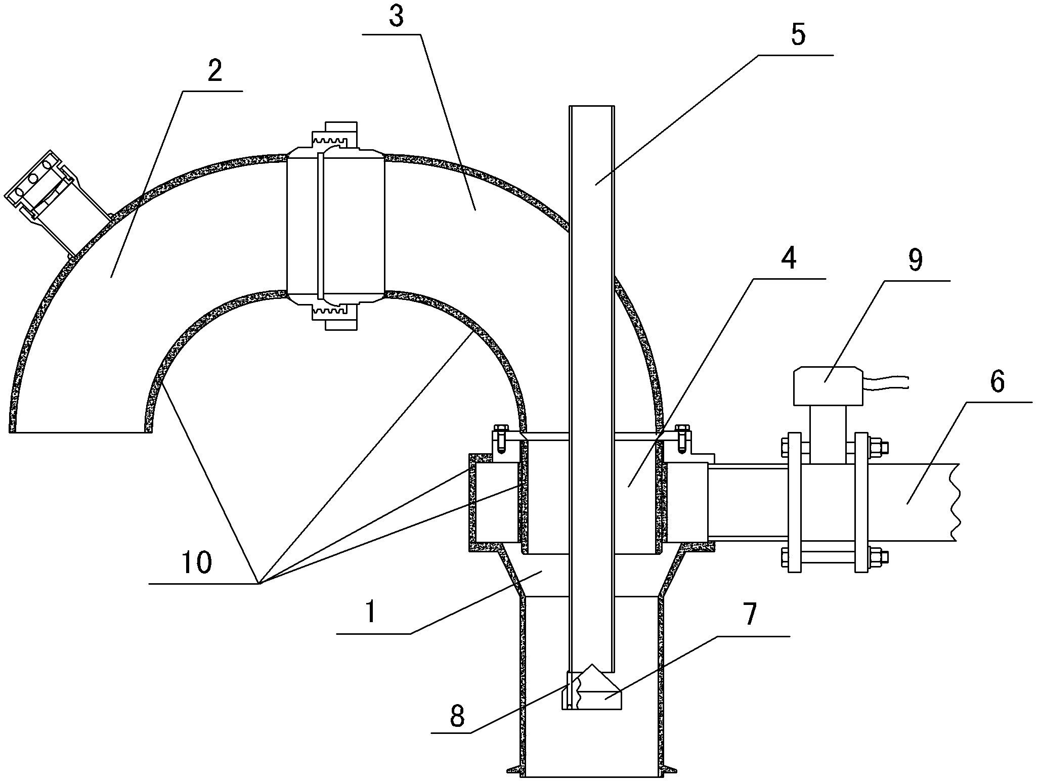
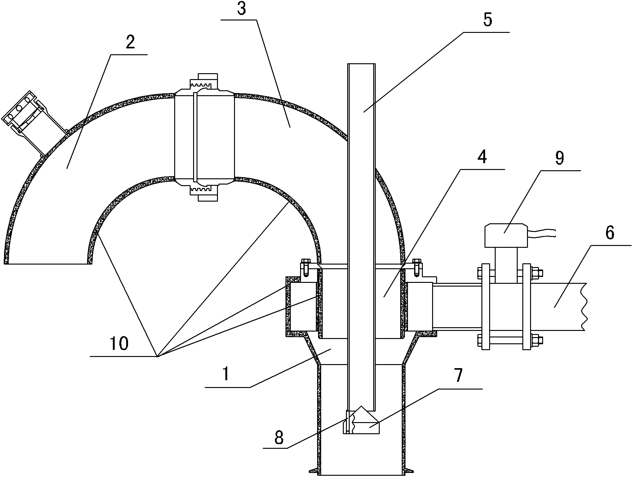
[0026] Embodiments of the present invention are further described below in conjunction with accompanying drawings:

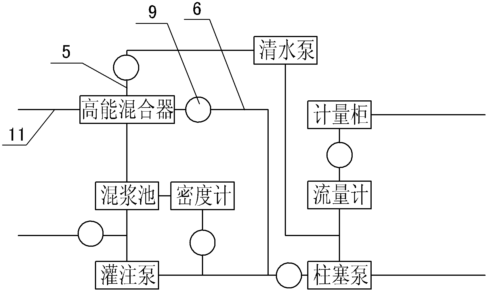
[0027] like Figure 1~2 As shown, the ash supply pipe 11 includes an upper ash elbow 2, an injection elbow 3 and a bushing 4, the bushing 4 is located inside the shell 1, the bottom end of the shell 1 is connected to the mud mixing tank, and the upper water pipe 5 is along the jet elbow. 3 The central direction of the outlet is welded together with the spray elbow 3, the water outlet end of the upper water pipe 5 is located at the lower part of the shell 1, the secondary ash mixing pipe 6 is connected to one side of the shell 1, and there is a branch below the water outlet end of the upper water pipe 5. The water thimble 7 and the water diversion thimble 7 are fixedly connected to the pipe wall of the upper water pipe 5 through the support pin 8. The secondary ash mixing pipe 6 is a single pipeline structure, and the secondary ash mixing pipe 6 is welded on the ...


PUM

PropertyMeasurementUnit
thicknessaaaaaaaaaa
hardnessaaaaaaaaaa

Abstract

The invention relates to a mixing equipment for well cementation in oil and gas fields, in particular to a high-energy mixer for well cementation in oil and gas fields, comprising a shell, a mortar supply pipe, a water supply pipe and a secondary mortar mixing pipe, wherein the secondary mortar mixing pipe is of a single pipeline structure; and a valve is installed on the secondary mortar mixing pipe. The secondary mortar mixing pipe is changed to be of the single pipeline structure in the high-energy mixer for well cementation in oil and gas fields,, so that the structure is simplified, the flow velocity of secondary mortar-mixed cement paste entering to the shell is increased and the blockage condition is avoided; a water-dividing thimble is fixed on the water supply pipe, so that the manual regulation is not needed, the labor intensity is reduced, the possible error is avoided during the manual regulation, the flow stability is ensured, the flow velocity is increased and the mortar mixing effect is improved; and a hard tungsten carbide alloy layer is coated on the inner wall of each pipe, so that the wear resistance is improved and the service life is prolonged.

Description

technical field [0001] The invention relates to a slurry mixing device used in well cementing in an oil and gas field, in particular to a high-energy mixer for well cementing in an oil and gas field. Background technique [0002] The high-energy mixer is the key component of the oilfield cementing vehicle for the initial mixing of cement ash and clean water. The high-energy mixers currently used generally have complex structures, easy blockage, low mixing efficiency, high labor intensity, and short service life. The reasons are as follows: [0003] 1. The secondary ash mixing pipe adopts the bull head type double pipeline structure, the structure is complex, and the cement slurry is easy to form blockage in the shell; [0004] 2. The water inlet of the upper water pipe needs to manually adjust the position of the water diversion thimble, which is labor-intensive, resulting in unstable water flow direction and velocity; [0005] 3. The mixer is welded and formed by common m...

Claims


Application Information

Patent Timeline
Patent Type & Authority Applications(China)
IPC IPC(8): E21B33/13
Inventor 何长秋王泽刚李克雷岳林
Owner SHANDONG VICTOR OILFIELD EQUIP
Learn More