Impeller of vortex air pump

An air pump and impeller technology, applied in the field of vortex air pump impeller and vortex air pump, can solve the problems of increasing production cost, difficult to remove burrs of blades, partitions and hubs, and increasing manufacturing difficulty, so as to reduce production difficulty, The effect of stable flow direction and improved dynamic balance performance

Inactive Publication Date: 2012-01-18
ZHEJIANG GREENCO IND
7 Cites 4 Cited by

AI-Extracted Technical Summary

Problems solved by technology

However, in the manufacturing process, it is still difficult to remove the burrs of the blades, separators and hubs, and the left and right blades are arranged symmetrically. During the manuf...

Method used

As shown in Figure 1, the impeller of this vortex air pump comprises disc-shaped wheel hub 1 and some uniformly fixed blades 2 on the outer circumference of wheel hub 1, and radially extends out annular shape on wheel hub 1 outer circumference. The partition plate 3, the blades 2 are distributed symmetrically along the partition plate 3 left and right and the blades 2 on the left and right sides are staggered at intervals. The hub 1, the blade 2 and the partition plate 3 are integrally formed by casting, which improves the strength of the overall structure.
[0025] There are reinforcing ribs 4 at the junction of the blade 2, the dividing plate 3 and the hub 1, and the reinforcing ribs 4 can be formed together in a block when casting. Since the par...

Abstract

The invention provides an impeller of a vortex air pump, belongs to the technical field of air pumps, and solves the problems that left and right blades of the conventional impeller are arranged symmetrically to influence dynamic balance, burrs are difficult to remove in the manufacturing processing procedure, and the like. The impeller for the vortex air pump comprises a disc-shaped hub and a plurality of blades which are uniformly and fixedly connected to the outer circumference edge of the hub, wherein an annular division board radially stretches out of the outer circumference of the hub; and the blades are distributed in a eudipleural mode along the division board, and the blades on left and right sides are staggered at intervals. The blades on the left and right sides are staggered at equal intervals, so that production difficulty is reduced, and the dynamic balance of the impeller is improved simultaneously.

Application Domain

Pump componentsPumps +2

Technology Topic

ImpellerEngineering +2

Image

  • Impeller of vortex air pump
  • Impeller of vortex air pump
  • Impeller of vortex air pump

Examples

  • Experimental program(1)

Example Embodiment

[0022] The following are specific embodiments of the present invention in conjunction with the accompanying drawings to further describe the technical solutions of the present invention, but the present invention is not limited to these embodiments.
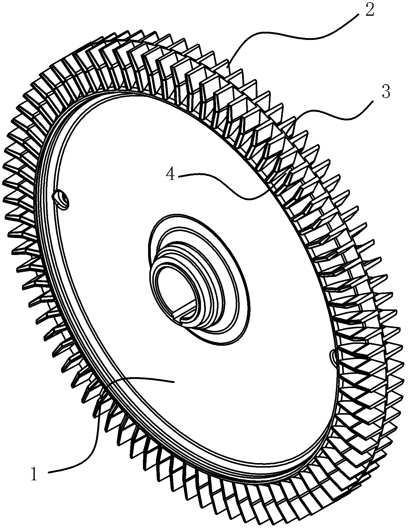
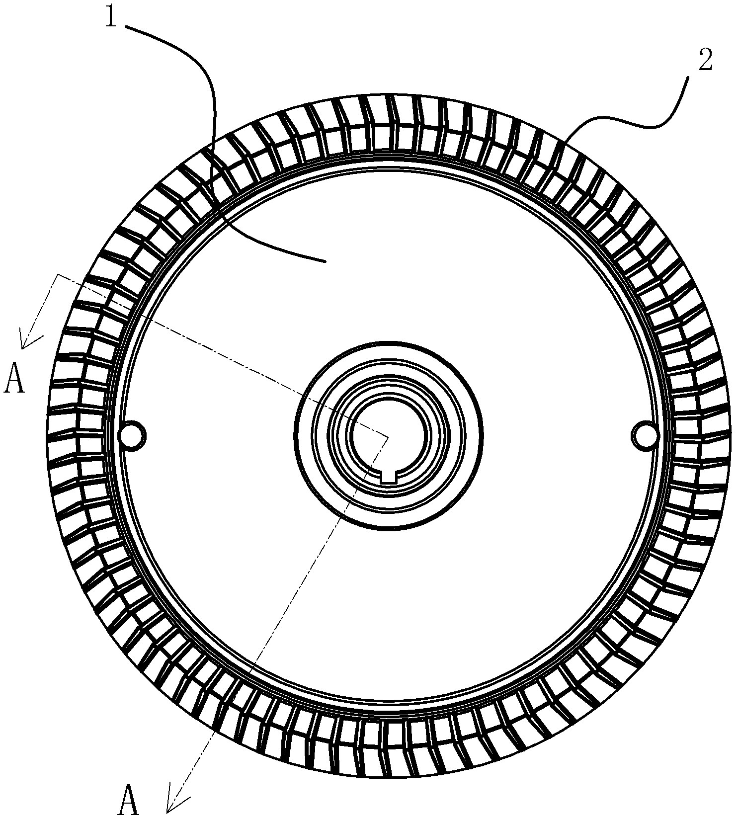
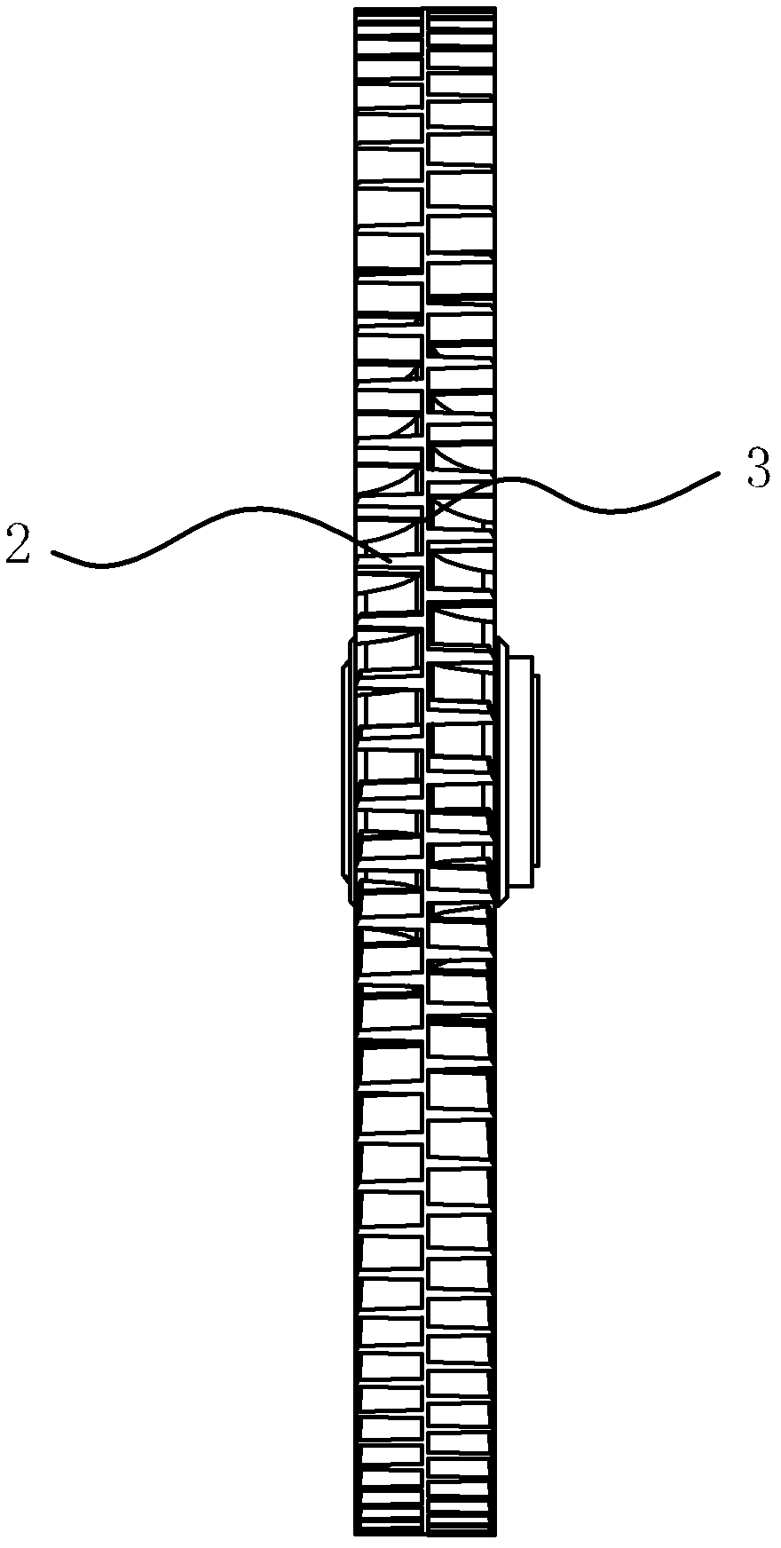
[0023] Such as figure 1 As shown, the impeller of the vortex air pump includes a disc-shaped hub 1 and a number of blades 2 uniformly fixed on the outer circumferential edge of the hub 1. An annular partition plate 3 extends radially on the outer circumference of the hub 1. The blades 2 are symmetrically distributed along the partition plate 3 and the blades 2 on the left and right sides are staggered. The hub 1, the blades 2 and the partition plate 3 are integrally formed by casting, which improves the strength of the overall structure.
[0024] Specifically, such as figure 2 , image 3 , Figure 4 As shown, the blade 2 in this embodiment is in the shape of a rectangular sheet and the blade 2 is in the shape of a curved surface with a relatively small amplitude. The blades 2 separated by the partition plate 3 are staggered at equal distances left and right, and the distance between two adjacent blades 2 on the same side of the partition plate 3 is 3 to 5 times the thickness of the blade 2. The outer edge of the partition plate 3 is flush with the outer edge of the blade 2, and the burrs on the outer edge of the partition plate 3 and the outer edge of the blade 2 can be removed at the same time when the burrs on the outer edge of the impeller are turned.
[0025] There are reinforcing ribs 4 at the junction of the blade 2, the partition plate 3 and the hub 1, and the reinforcing ribs 4 are formed into blocks and can be formed together during casting. Since the partition plate 3 is perpendicular to the outer surface of the hub 1, and the blade 2 is basically perpendicular to the outer surface of the hub 1 and the partition plate 3, it is difficult to remove the burrs in the right-angle corners where the three are connected. After the reinforcing rib 4 is provided, the problem of removing burrs is eliminated, and the strength of the junction of the blade 2, the partition plate 3 and the hub 1 is also strengthened, and the connection of the three is stronger.
[0026] In order to enhance the pressurization strength of the blade 2 to the airflow, the blade 2 adopts a curved shape, and the blade 2 can better store air, so that the airflow is subjected to a strong centrifugal force when it moves to the edge of the impeller.
[0027] The specific embodiments described herein are merely examples to illustrate the spirit of the present invention. Those skilled in the art to which the present invention pertains can make various modifications or additions to the specific embodiments described or use similar alternatives, but they will not deviate from the spirit of the present invention or exceed the definition of the appended claims. Range.
[0028] Although this article uses more terms such as hub 1, blade 2, partition plate 3, and stiffener 4, the possibility of using other terms is not excluded. These terms are used only to describe and explain the essence of the present invention more conveniently; to interpret them as any additional limitation is contrary to the spirit of the present invention.

PUM

no PUM

Description & Claims & Application Information

We can also present the details of the Description, Claims and Application information to help users get a comprehensive understanding of the technical details of the patent, such as background art, summary of invention, brief description of drawings, description of embodiments, and other original content. On the other hand, users can also determine the specific scope of protection of the technology through the list of claims; as well as understand the changes in the life cycle of the technology with the presentation of the patent timeline. Login to view more.

Similar technology patents

Annuloplasty Device and Methods

ActiveUS20190209320A1high strength
Owner:DRASLER WILLIAM JOSEPH +1

Carbon/carbon composite microsphere material, production method and lithium ion battery

ActiveCN103214245ASmall specific surface areahigh strength
Owner:INST OF PROCESS ENG CHINESE ACAD OF SCI

Classification and recommendation of technical efficacy words

  • high strength
  • increase load

Method and apparatus for network function virtualization

ActiveUS20160366014A1reduce investment costincrease load
Owner:KT CORP

Method for Producing 1,3,3,3-Tetrafluoropropene

ActiveUS20090099395A1increase loadsmall load
Owner:CENT GLASS CO LTD

Hybrid wobbe control during rapid response startup

ActiveUS20100275609A1increase load
Owner:GENERAL ELECTRIC CO

Circular granular sludge reactor

Owner:山东美泉环保科技有限公司
Why Eureka
Try Eureka