
Polarization sensitive distributive optical frequency domain reflection disturbance sensor and demodulation method

An optical frequency domain reflection and sensing device technology, applied in the field of optical fiber sensing, can solve the problems of low spatial resolution, short test distance, single point separation, etc., and achieve the effect of high sensitivity and high signal-to-noise ratio

Active Publication Date: 2013-06-05
TIANJIN UNIV
View PDF6 Cites 5 Cited by
  • Summary
  • Abstract
  • Description
  • Claims
  • Application Information

AI Technical Summary

Problems solved by technology

[0005] The purpose of the present invention is to solve the problems of short test distance (less than 80km), low spatial resolution (greater than 10m) and single-point separation in the prior art, and provide a polarization-sensitive distributed optical frequency domain reflection disturbance sensing device and solution tune method

Method used


Image

  • Polarization sensitive distributive optical frequency domain reflection disturbance sensor and demodulation method
  • Polarization sensitive distributive optical frequency domain reflection disturbance sensor and demodulation method
  • Polarization sensitive distributive optical frequency domain reflection disturbance sensor and demodulation method

Examples


Embodiment 1

[0055] Example 1: Polarization-sensitive distributed optical frequency domain reflection disturbance sensing device

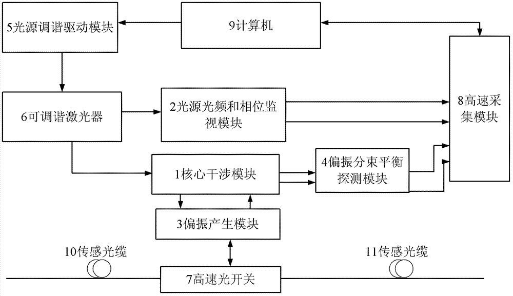
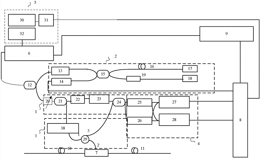
[0056] Such as figure 1 As shown, the basic structure of the core interference module 1 is a Mach-Zehnder (Mach Zehnder) interferometer structure, which constitutes an optical heterodyne interference structure; the light source optical frequency and phase monitoring module 2, which mainly collects the real-time optical frequency and phase of the laser , to perform nonlinear scanning and phase noise compensation on the signal of the core interference module; the polarization generation module 3 and the polarization beam splitting balance detection module 4 realize the extraction of polarization information in the sensing optical cable; the light source tuning drive module 5 and the tunable laser 6 Provide high-speed and narrow-linewidth laser light sources with linear scanning wavelengths for polarization-sensitive distributed optical frequency domain reflecti...

Embodiment 2

[0071] Example 2: Polarization-sensitive distributed optical frequency domain reflection disturbance sensing method

[0072] Its specific technical methods and algorithms include several steps:

[0073] The first step, the real-time phase optical frequency acquisition of the laser, performs Hilbert transformation or trigonometric function transformation and time-frequency domain transformation on the signal collected by the light source optical frequency and phase monitoring module to obtain the optical frequency or phase of the laser at each time point;

[0074] The second step is to use the optical frequency or phase signal of the laser collected in real time in the first step, and use the non-uniform fast Fourier transform or compensation interpolation algorithm to perform phase compensation on the two signals of the core interference module including the polarization eigenstate. , to suppress the impact of optical frequency nonlinearity and light source phase noise on th...


PUM


Abstract

This invention relates to a distributed disturbance sensing device based on polarization sensitive optical frequency domain reflectometry (OFDR) and the related demodulation thereof. The device, adopting OFDR, polarization controlling and analysis techniques, consists of a ultra-narrow linewidth tunable laser source module, polarization generating and polarization splitting balanced detecting module, laser source optical frequency and phase monitoring module, high-speed optical switch and so on to establish a large-scale and long-distance optical sensing network. The demodulation method consists of analysis the polarization information from sensing optical fiber, the method of suppressing and compensating of the non-linear optical frequency and the laser phase noise, super-resolution analyzing, advanced denoising method and the polarization information analysis method based on Jones and Mueller's matrices using distributed wave plate model of optical fiber.

Description

technical field [0001] The invention belongs to the technical field of optical fiber sensing. The invention is applied to long-distance optical fiber distributed disturbance and stress sensing, and relates to a polarization-sensitive distributed optical frequency domain reflection disturbance sensing device and method. Background technique [0002] At present, the main technical solutions for long-distance optical fiber distributed disturbance and stress sensing include laser interference method, phase-sensitive optical time-domain reflection method and polarization-sensitive optical time-domain reflection method. These methods all have short test distances (<80km) , This topic is aimed at the current all-fiber distributed disturbance sensing technology: short test distance (less than 80km), low spatial resolution (greater than 10m), single-point separation and other defects. [0003] Due to the shortcomings of the above-mentioned technologies, a polarization-sensitive o...

Claims


Application Information

Patent Timeline
Patent Type & Authority Patents(China)
IPC IPC(8): G01D5/30
CPCG01M11/3172G01D5/353G01D5/35329G01H9/004G01M11/3181G01D5/35325G01D5/35354
Inventor 刘铁根刘琨丁振扬江峻峰李定杰
Owner TIANJIN UNIV
Learn More