Manufacturing method for holographic dual-blazed grating

A technology of a blazed grating and a manufacturing method, which is applied in the field of the preparation of diffractive optical elements, can solve the problems such as the difficulty of precise control of the duty ratio, the groove shape and the groove depth, the inability to achieve precise control, and the inconsistent etching rate, etc. Avoid secondary photoresist lithography process, good etching effect, and achieve the effect of precise control

Active Publication Date: 2012-01-18
SUZHOU UNIV
View PDF5 Cites 27 Cited by
  • Summary
  • Abstract
  • Description
  • Claims
  • Application Information

AI Technical Summary

Problems solved by technology

Due to the grating formed after the photoresist passes through the photolithography process, it is difficult to precisely control its occupation ratio, groove shape and groove depth

Method used


Image

  • Manufacturing method for holographic dual-blazed grating
  • Manufacturing method for holographic dual-blazed grating
  • Manufacturing method for holographic dual-blazed grating

Examples


Embodiment 1

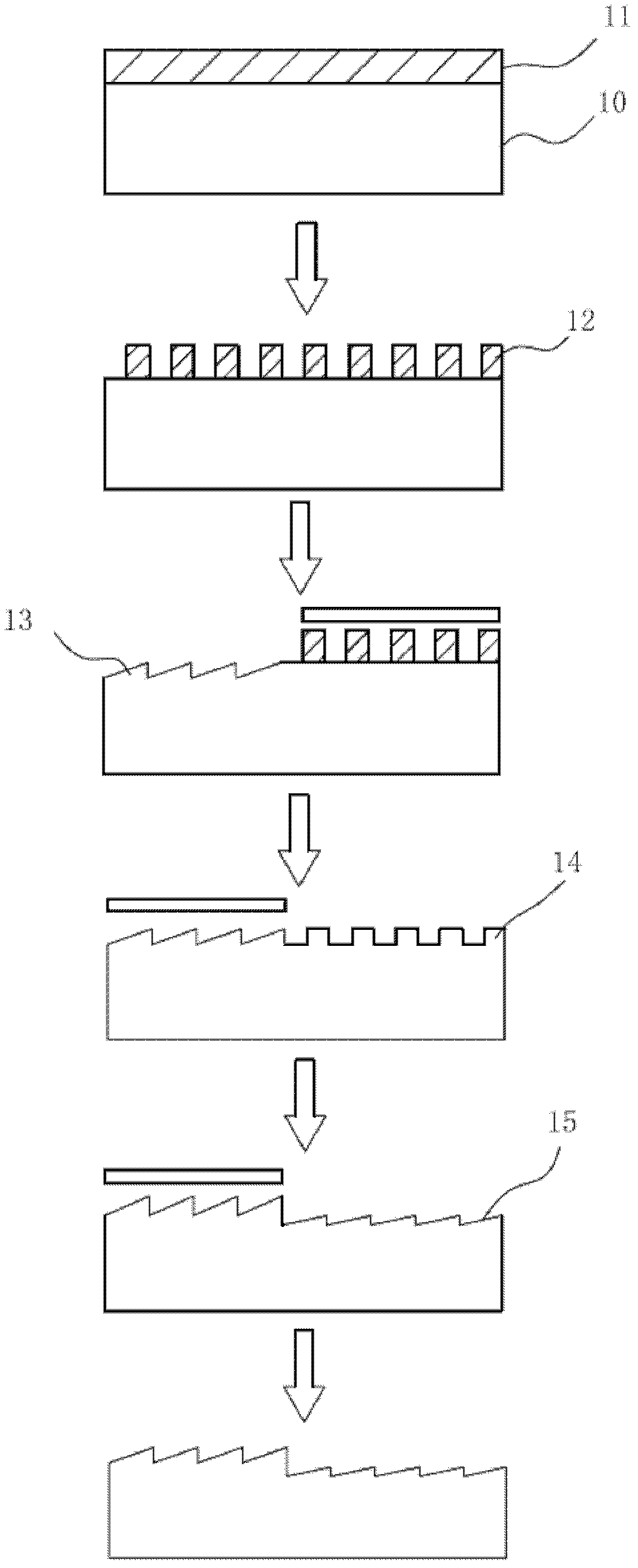
[0062] Example 1: Please refer to image 3 , image 3 It is a schematic diagram of states corresponding to each step in the first embodiment of the present invention. Fabricate a holographic double blazed grating with a grating period of 833 nanometers and two blaze angles of 25° and 10° respectively, using interference exposure, ion beam etching and inclined ion beam scanning etching, including the following steps:

[0063] (1) Coating photoresist 11 on the substrate 10, according to the requirements of the double blazed grating that needs to be made, that is, the grating period (Λ) is 833 nanometers, and the two blazed angles are 25° and 10° respectively. According to the empirical formula of blaze angle θs and groove shape and ion beam incident angle, θs≈α-3°.

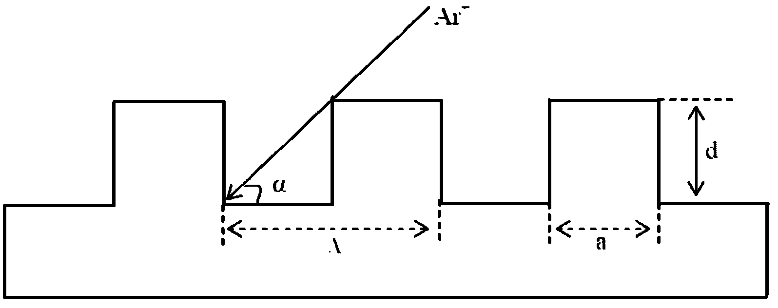
[0064] Using a rectangular photoresist grating (see attached figure 2 ) as an example, first make a 25° blaze angle (A blaze angle) grating, generally, the duty ratio f=a / Λ=0.5, by the formula:

[0065] ...

Embodiment 2

[0075] Example 2: Please refer to Figure 4 , Figure 4 It is a schematic diagram of states corresponding to each step in the second embodiment of the present invention. Fabricate a holographic double blazed grating with a grating period of 1000 nanometers and two blaze angles of 25° and 12° respectively, using interference exposure, forward ion beam etching and oblique Ar ion beam scanning etching, including the following steps:

[0076] (1) Coating photoresist 21 on the substrate 20, according to the requirements of the double blazed grating that needs to be made, that is, the grating period (Λ) is 1000 nanometers, and the two blazed angles are 25° and 12° respectively. According to the empirical formula of blaze angle θs and groove shape and ion beam incident angle, θs≈α-3°.

[0077] Using a sinusoidal photoresist grating (see attached Figure 5 ) as an example, at first make a 25 ° blaze angle (A blaze angle) grating, the duty ratio f=a / Λ=0.5 of this grating, the profil...

Embodiment 3

[0090] Example 3: Please refer to Figure 7 , Figure 7 It is a schematic diagram of states corresponding to each step in the third embodiment of the present invention. In this embodiment, the striped plate 37 is used for shielding, so that the two blazed angles A and B of the double blazed grating are distributed alternately, as shown in Figure 7 shown. Fabricate a holographic double blazed grating with a grating period of 500 nanometers and two blaze angles of 20° and 10° respectively, using interference exposure, ion beam etching and inclined ion beam scanning etching, including the following steps:

[0091] (1) Coating photoresist 31 on the substrate 30, according to the requirements of the double blazed grating that needs to be made, that is, the grating period (Λ) is 500 nanometers, and the two blazed angles are 20° and 10° respectively. According to the empirical formula of blaze angle θs and groove shape and ion beam incident angle, θs≈α-3°.

[0092] Taking a rect...


PUM


Abstract

The invention discloses a manufacturing method for a holographic dual-blazed grating. The two blaze angles of the holographic dual-blazed grating are respectively a blaze angle A and a blaze angle B. Different control of the two blaze angles is realized by performing oblique ion beam etching by using a photoresist grating and a homogenous grating as masks on two grating areas A and B, so that a secondary photoresist photoetching process is avoided. When the homogenous grating is manufactured, the positive ion beam etching time can be controlled so that the groove depth of the homogenous grating is controlled precisely. In addition, the homogenous grating mask and the substrate are made of the same material, and the etching rate of the homogenous grating mask and the etching rate of the substrate are kept consistent all the time, so that precise control of the blaze angles can be realized.

Description

technical field [0001] The invention relates to a preparation method of a diffractive optical element, in particular to a preparation method of a holographic double blazed grating. Background technique [0002] Grating is a very widely used and important high-resolution dispersive optical element, which occupies a very important position in modern optical instruments. [0003] As we all know, the principal maximum direction of diffraction by a single grating is actually not only the geometrical optics propagation direction of light, but also the zero-order direction of the entire multi-slit grating. It concentrates light energy, but cannot separate various wavelengths. In practical applications, Focus on concentrating as much light energy as possible on a specific order. For this reason, it is necessary to make the diffraction grating into a groove shape determined by calculation, so that the main maximum direction of the diffraction of a single grating groove (or the direc...

Claims


Application Information

Patent Timeline
IPC IPC(8): G02B5/18G03F7/00
CPCG01J3/1838G02B5/32G02B5/203G03F7/00G03F7/0005G02B5/1857G02B5/18G03H1/0244G03H1/0476G03H1/182G03H2001/0439G03H2224/04G03H2260/14G03H2260/63G02B5/1842G02B5/1847G02B5/1861G03H1/0402G03H1/181
Inventor 刘全吴建宏陈明辉
Owner SUZHOU UNIV
Why Eureka
Try Eureka