
Heat treatment process of storage battery grid

A battery and grid technology, applied in lead-acid battery electrodes and other directions, can solve the problems of short life, poor battery consistency, unstable grid physical and chemical properties, etc., to improve the crystal phase structure, reduce ohmic internal resistance, improve Effects of consistency and stability

Inactive Publication Date: 2012-01-18
TIANNENG BATTERY GROUP +4
View PDF4 Cites 13 Cited by
  • Summary
  • Abstract
  • Description
  • Claims
  • Application Information

AI Technical Summary

Problems solved by technology

[0003] The invention provides a heat treatment process for battery grids, which solves the problems of poor consistency and short service life of batteries due to unstable physical and chemical properties of the grids

Method used


Image

  • Heat treatment process of storage battery grid

Examples

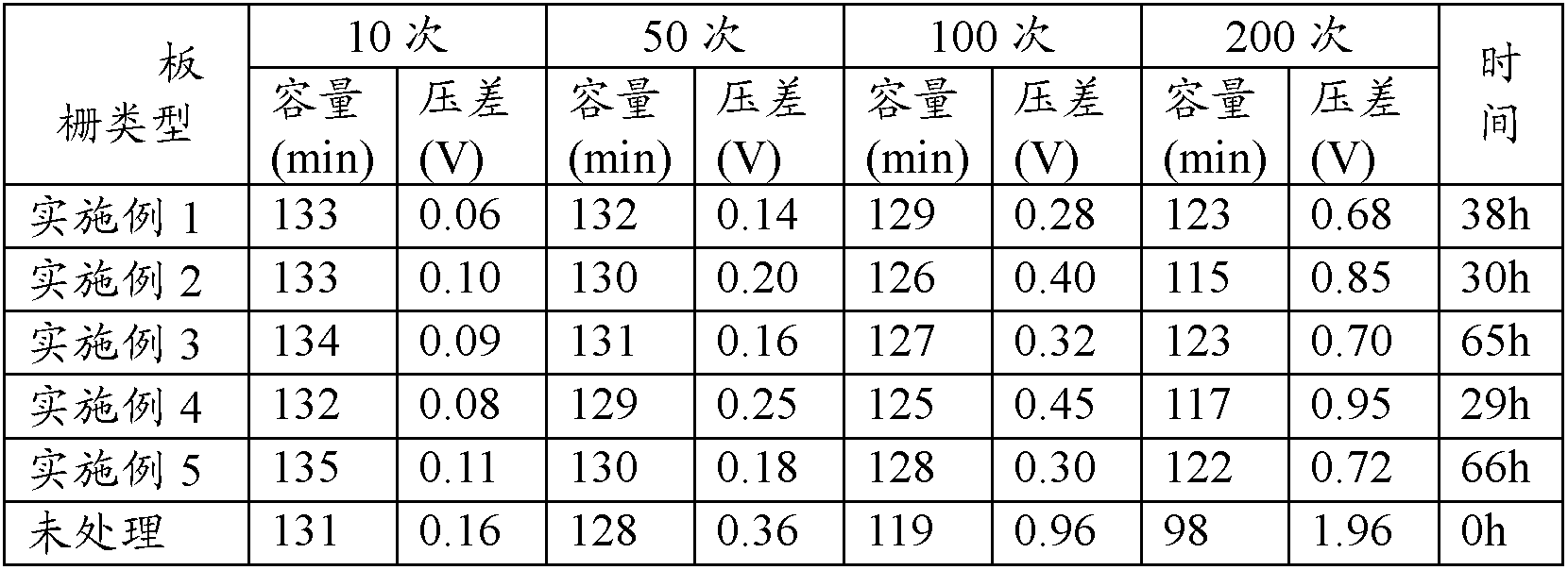

Embodiment 1

[0012] In the first stage, the newly cast grid is put into the curing room, and CO is introduced into the curing room 2 , so that the CO in the curing chamber 2 The volume concentration reaches 13%, and then steam is introduced to heat and humidify, so that the temperature in the curing room reaches 70°C and the humidity reaches 98%, and lasts for 24 hours.

[0013] In the second stage, the grid is transferred to the drying room. The temperature in the drying room is 85°C, stored for 4 hours, cooled naturally, and stored in a ventilated environment at room temperature for 10 hours before coating.

Embodiment 2

[0015] In the first stage, the newly cast grid is put into the curing room, and CO is introduced into the curing room 2 , so that the CO in the curing chamber 2 The volume concentration reaches 15%, and then steam is introduced to heat and humidify, so that the temperature in the curing room reaches 65°C and the humidity reaches 99%, and lasts for 12 hours.

[0016] In the second stage, the grid is transferred to the drying room. The temperature in the drying room is 80°C, stored for 6 hours, cooled naturally, and stored in a ventilated environment at room temperature for 12 hours before coating.

Embodiment 3

[0018] In the first stage, the newly cast grid is put into the curing room, and CO is introduced into the curing room 2 , so that the CO in the curing chamber 2 The volume concentration reaches 18%, and then the steam is heated and humidified, so that the temperature in the curing room reaches 60°C and the humidity reaches 99%, and lasts for 48 hours.

[0019] In the second stage, the grid is transferred to the drying room. The temperature in the drying room is 90°C, stored for 2 hours, cooled naturally, and stored in a ventilated environment at room temperature for 15 hours for coating.


PUM


Abstract

The invention discloses a heat treatment process of a storage battery grid. The process comprises the following steps: (1) placing the grid that is just cast and molded in a curing chamber for 12-48 hours, wherein the humidity of the curing chamber is not less than 98%, the CO2 concentration of the curing chamber is not less than 13% and the temperature of the curing chamber is 60-70 DEG C; (2) placing the grid in a drying chamber with the temperature of 80-90DEG C for 2-6 hours; (3) naturally cooling and then placing the grid in a room-temperature ventilated environment for no less than 10 hours. According to the method, the grid can be placed in different environments for realizing chemical reaction and lattice parameter variation, so that a layer of rough basic carbonate and carbonate is generated on the surface of the grid, the bonding strength of the grid with active substances can be increased, the crystalline phase structure of a grid alloy can be improved, the battery plate ohm internal resistance can be reduced, and then consistency and stability of the electrochemical performances of the battery plate can be improved greatly.

Description

technical field [0001] The invention relates to the technical field of battery manufacturing, in particular to a heat treatment process for battery grids. Background technique [0002] The manufacturing process of the traditional lead-acid battery plates for power is generally as follows: firstly, the grid is cast by gravity, and then the grid is hardened naturally (more than three days), and finally the surface of the grid is coated with lead paste, cured and dried to obtain a raw material. plate. If the quality state of the grid is not well controlled, the physical and chemical properties of the plate will be very unstable, the early capacity fading of the plate will occur, the binding force between the active material and the grid will be poor, the impedance of the plate will be large, and the utilization rate of the active material will decrease, etc. The problem will eventually lead to poor consistency and short life of the battery. Contents of the invention [0003...

Claims


Application Information

Patent Timeline
IPC IPC(8): H01M4/21
CPCY02E60/126Y02E60/10
Inventor 陈清元张天任朱健代飞刘峰陈芬娣赵海敏宋文龙
Owner TIANNENG BATTERY GROUP
Learn More