Coaxial magnetic gear

A magnetic gear, coaxial technology, applied in electrical components, electromechanical devices, etc., can solve the problems of restricting the application of coaxial magnetic gears, reducing the mechanical bearing force of the rotor, and low torque density of magnetic gears, achieving convenient processing and manufacturing, improving The effect of high mechanical endurance and mechanical strength

Active Publication Date: 2012-01-18
SOUTHEAST UNIV
View PDF7 Cites 25 Cited by
  • Summary
  • Abstract
  • Description
  • Claims
  • Application Information

AI Technical Summary

Problems solved by technology

At present, the traditional coaxial magnetic gear includes an outer rotor arranged from the outside to the inside with a coaxial center, a magnetic adjustment ring and an inner rotor. Both the inner and outer rotors adopt a surface-mounted permanent magnet structure, which not only reduces the mechanical bearing capacity of the rotor, Moreover, the surface-mounted permanent magnets are easy to fall off when the rotor rotates
At the same time, the magnetic adjusting ring is composed of magnetically permeable blocks and non-magnetically permeable blocks arranged at intervals. Since there is a two-layer air gap between the magnetically adjusting ring and the inner and outer rotors, the torque density of the magnetic gear is low, which is limited by various reasons. Application of traditional coaxial magnetic gear

Method used


Image

  • Coaxial magnetic gear
  • Coaxial magnetic gear
  • Coaxial magnetic gear

Examples


Embodiment Construction

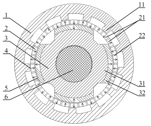
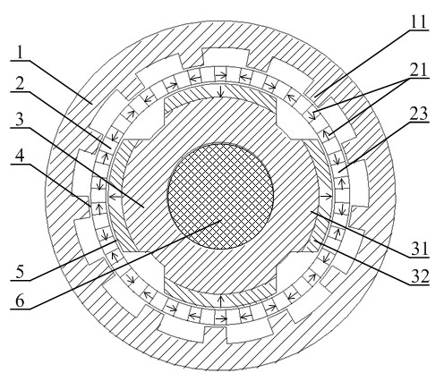
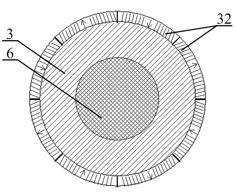
[0026] The coaxial magnetic gear of the present invention comprises an outer rotor 1, a stationary magnetic ring 2, an inner rotor 3 and a rotating shaft 6 arranged from outside to inside with a coaxial center; the outer rotor 1 is an annular magnetizer, and on its inner ring Equidistantly arranged outer rotor salient poles 11 are provided; the stationary magnetic ring 2 is an annular component composed of magnetic ring permanent magnets 21 arranged at equidistant intervals, and a non-conductive magnet is arranged between two adjacent magnetic ring permanent magnets 21. Block 22, the magnetic ring permanent magnet 21 is radially magnetized, and the magnetization direction of adjacent permanent magnets is opposite; the inner rotor 3 is fixed on the rotating shaft 6, and the outer ring of the inner rotor is provided with inner rotors arranged at equal intervals. The rotor permanent magnet 32 ​​; the outer air gap 4 is provided between the outer rotor salient pole 11 and the stati...


PUM


Abstract

The invention discloses a coaxial magnetic gear comprising an external rotor, a static magnetic ring and an internal rotor which are lined from outside to inside and share the same axis. The external rotor is a circular magnetic conductor, and external rotor convex poles which are lined with equal spacing are arranged on the inner ring of the external rotor; the static magnetic ring is fixedly arranged between the internal rotor and the external rotor, and comprises permanent magnets and non-permanent magnets which are lined at intervals; internal rotor convex poles are lined on the outer ring of the internal rotor with equal spacing, and internal rotor permanent magnet bodies are arranged on the outer ring of the internal rotor; the internal rotor can be also in other structural forms capable of producing effective N-S magnetic poles; and in order to ensure the normal rotation of the internal rotor and the external rotor, air gaps are left between the three parts. Through the convex pole structure of the external rotor, the coaxial magnetic gear enables a static magnetic ring magnetic field to modulate a series of harmonic rotation magnetic fields on an inner air gap side, the number of the polar pairs of the selected internal rotor permanent magnet bodies is the same with that of the pole pairs of a required harmonic magnetic field, and the stable torque transmission is realized by the coupling action of the polar pairs of the selected internal rotor permanent magnet bodies and the pole pairs of a required harmonic magnetic field. The magnetic gear has the characteristics of high torque density, high mechanical strength of the external rotor, and convenience in processing and manufacturing.

Description

technical field [0001] The invention belongs to the electromechanical field, and relates to a coaxial magnetic gear suitable for non-contact variable speed driving occasions. Background technique [0002] In industrial applications, many occasions that require variable speed drives are usually realized by mechanical devices such as bulky gearboxes. The use of a large number of mechanical devices will inevitably bring about problems such as noise, vibration, friction loss and regular maintenance, and will significantly increase the complexity, volume and weight of the system. In addition, mechanical gears do not have overload self-protection capabilities, and safety accidents are prone to occur when the transmitted torque exceeds the gear's bearing capacity. [0003] In comparison, the magnetic gear is a non-contact transmission device, which does not have problems such as noise, vibration, friction loss and lubrication, and can realize physical isolation between input and o...

Claims


Application Information

Patent Timeline
Patent Type & Authority Applications(China)
IPC IPC(8): H02K16/02
Inventor 程明李祥林邹国棠花为杜怿
Owner SOUTHEAST UNIV
Why Eureka
Try Eureka