
Brake system having simultaneous or partially simultaneous pressure generation and reduction in the wheel brakes from differing wheel cylinder pressure levels

A technology of wheel brakes and braking systems, applied in the direction of brakes, brake transmissions, vehicle components, etc., can solve the problems of not providing pressure generation, pressure reduction, pressure increase, etc.

Active Publication Date: 2012-01-18
IPGATE
View PDF7 Cites 25 Cited by
  • Summary
  • Abstract
  • Description
  • Claims
  • Application Information

AI Technical Summary

Problems solved by technology

[0004] Despite these measures described in EP 06724475, the multiplexing method has the disadvantage that in the case of unequal pressure levels in the two wheel brakes a simultaneous pressure reduction is not possible, as described in EP 06724475 With the described sizing, if the flow resistance from HZ or THZ to the wheel cylinders is too small, pressure equalization can occur between two to four wheel brakes during pressure reduction
[0006] Furthermore, simultaneous pressure generation is not provided in EP 06724475
This creates the fact that a possible pressure increase may not be performed for a while and may result in a longer braking path

Method used


Image

  • Brake system having simultaneous or partially simultaneous pressure generation and reduction in the wheel brakes from differing wheel cylinder pressure levels
  • Brake system having simultaneous or partially simultaneous pressure generation and reduction in the wheel brakes from differing wheel cylinder pressure levels
  • Brake system having simultaneous or partially simultaneous pressure generation and reduction in the wheel brakes from differing wheel cylinder pressure levels

Examples


Embodiment Construction

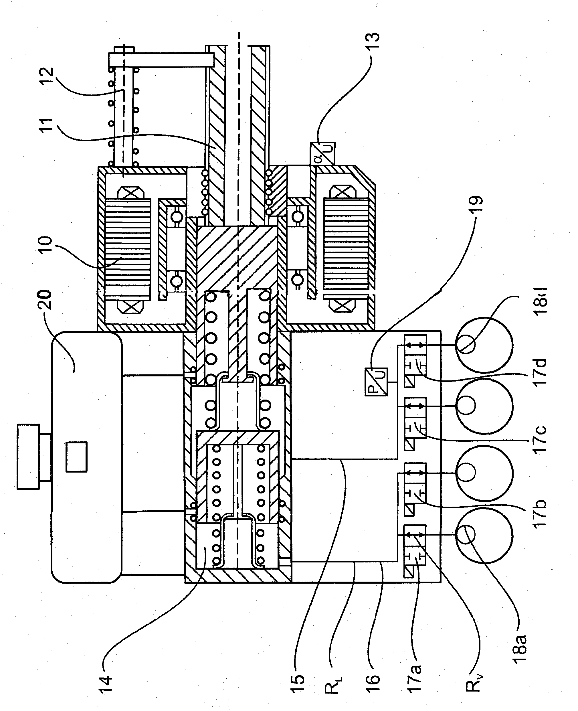
[0034] figure 1 The basic structure of the braking system according to the invention is shown, which consists of HZ or THZ 14, EC motor 10, main shaft 11 for driving the pressure rod piston, main shaft reset device 12 and rotational angle sensor 13 which determines position of the piston and detect rotor position or piston travel.

[0035] If the piston receives an adjustment command to generate a specific pressure, a corresponding piston movement is generated by the pre-recorded pressure-volume characteristic stored in the characteristic map, by the position sensor 13 and the pressure sensor 19 in the pressure rod circuit. In the case of a subsequent brief constant pressure, which is generally the case during a braking operation, a correlation comparison is carried out on the basis of new measurement data using the stored characteristic map data. If there are deviations, when the vehicle is at a standstill at a later time, the pressure-volume characteristic is recorded again...


PUM


Abstract

The invention relates to a braking system having a brake booster, the piston-cylinder system (14, HZ, THZ) thereof being driven by an electrical motor, wherein at least one working chamber of the piston-cylinder system (14, HZ, THZ) is in connection to at least two wheel brakes via hydraulic lines, wherein a 2 / 2-way switching valve (17a, 17b, 17c, 17d) is allocated to each wheel brake and the hydraulic connection lines between the wheel brakes (18a, 18b, 18c, 18d) and the piston-cylinder system (14, HZ) are separately or commonly closable by means of the 2 / 2-way switching valves (17a, 17b, 17c, 17d), such that a pressure can be adjusted in the wheel brakes (18a, 18b, 18c, 18d) one after another in terms of a multiplexer process and / or simultaneously, wherein the electrical motor and the switching valves (17a, 17b, 17c, 17d); are activated by a control device and the hydraulic connection line from the working chamber of the piston-cylinder system (14, HZ, THZ) to the respective magnetic valve has a flow resistance RLi and each switching valve has a flow resistance RVi together with the hydraulic line to the wheel cylinder (17a, 17b, 17c, 17d), wherein the flow resistances RLi and RVi are small, such that the HZ piston speed determines the pressure reduction gradients and pressure generation gradients in each wheel brake (18a, 18b, 18c, 18d), wherein the flow resistance RLi is smaller than the flow resistance RVi and the control device regulates or activates the piston movement and piston speed during pressure generation and pressure reduction in dependence on the pressure-volume characteristic curve of the wheel brakes (18a, 18b, 18c, 18d).

Description

technical field [0001] The invention relates to a brake system according to the preamble of claim 1 . Background technique [0002] In ABS / ESP, the precision and dynamics of the pressure progression determine the quality of the control and thus the braking path and vehicle stability. Rapid and precise pressure control is decisive for good control. With the exception of the electromechanical brake EMB, all hydraulic systems work with 2 / 2-way solenoid valves. The bibliographical information on pages 114-119 of Brakes Handbook, 2nd Edition, 2004 provides detailed basic information on this point. Without special measures, these valves have a purely digital switching behavior, ie they are either open or closed (open / closed). As a result of the rapid closing, pressure oscillations of large magnitude occur, depending on the pressure gradient, which affect the wheel performance and above all cause noise. In this case, the pressure gradient depends on the strongly fluctuating pre...

Claims


Application Information

Patent Timeline
Patent Type & Authority Applications(China)
IPC IPC(8): B60T8/32B60T13/74
CPCB60T8/3265B60T8/4077B60T13/745B60T8/1761B60T8/32B60T8/40B60T8/44B60T13/74
Inventor 海因茨·莱贝尔安东·万赞滕克里斯蒂安·克格尔施佩格
Owner IPGATE
Learn More