Energy-feedback tractive power supply system with high power factor and high cost performance

A traction power supply system, high power factor technology, applied in the direction of reactive power adjustment/elimination/compensation, power lines, reactive power compensation, etc., can solve problems such as large fluctuation range, energy waste, poor overload capacity, etc., to achieve power improvement factor, reducing current harmonics, and strong overload capacity

Inactive Publication Date: 2012-01-25
BEIJING QIANSIYU ELECTRIC +1
View PDF3 Cites 23 Cited by
  • Summary
  • Abstract
  • Description
  • Claims
  • Application Information

AI Technical Summary

Problems solved by technology

It is characterized by simple system structure, high power density, and low equipment cost, but the DC voltage is uncontrollable and has a large fluctuation range; at the same time, the energy can only be transmitted in one direction, and the excess energy of the regenerative braking of the train cannot be fed back to the AC grid. The dynamic resistance is consumed, resulting in a waste of energy
The energy-feedback traction power supply device based on high-power PWM rectifier is used to completely replace the diode rectifier unit, which can not only ensure the stability of the DC grid, improve the quality of power supply, but also realize the feedback of the train braking energy to the AC grid, and avoid the consumption of braking energy on the resistor. , to save energy, but the high price of PWM rectifiers, large volume, poor overload capacity and other constraints make it difficult to popularize and apply PWM rectifiers to completely replace diode rectifiers.

Method used


Image

  • Energy-feedback tractive power supply system with high power factor and high cost performance
  • Energy-feedback tractive power supply system with high power factor and high cost performance
  • Energy-feedback tractive power supply system with high power factor and high cost performance

Examples


Embodiment Construction

[0025] The following is an example of a traction power supply system with a subway line length of 20 kilometers and 8 energy-feedback substations.

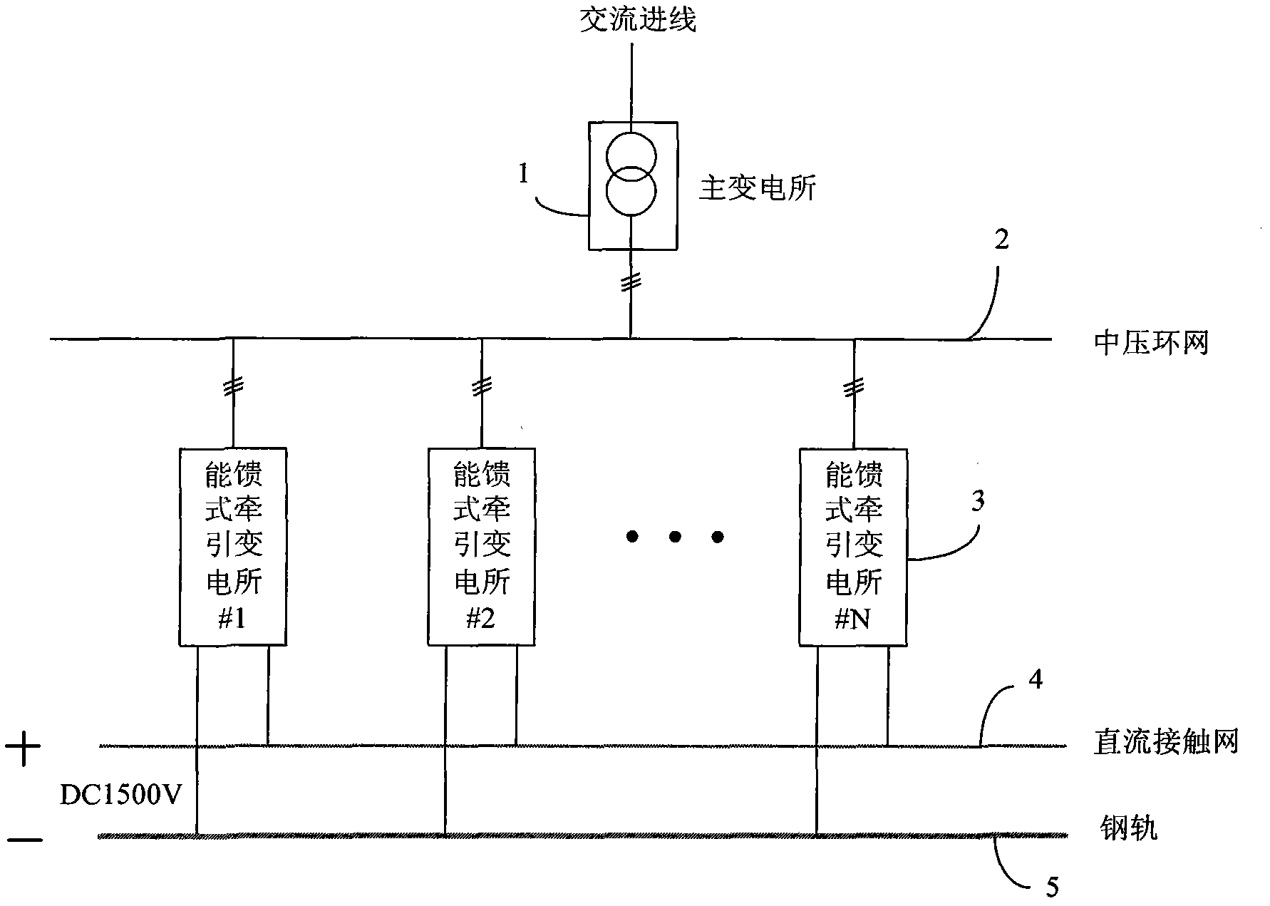
[0026] The whole traction power supply system adopts such as figure 1 The main circuit topology shown. in:

[0027] The main equipment in the main substation is a large-capacity oil-immersed transformer, which is used to convert the input 110kV high voltage into the medium-voltage ring network 35kV voltage, which is used by the energy-fed traction substations on the line. The transformer capacity is 60MVA.

[0028] The medium-voltage ring network adopts 35kV XLPE insulated power cables, which are laid along the subway lines, and are used to transmit and distribute electric energy from the main substation to various energy-fed traction substations. With the adoption of regenerative traction substations, excess train braking energy can also be fed back to the medium-voltage ring network and reused by other substations to achieve ...


PUM


Abstract

The invention discloses an energy-feedback tractive power supply system with high power factor and high cost performance, relating to an energy-feedback tractive power supply system. The system comprises a main substation, a medium-voltage ring network, a first to an Nth energy-feedback tractive substations, a direct-current contact network and a steel rail. In the energy-feedback tractive substations, a set of 12-pulse-wave rectifier unit and a set of PWM (Pulse Width Modulation) unit are connected in parallel; by sufficiently utilizing respective advantages of the rectifier unit and the PWM unit, bidirectional flow of energy is realized on the one hand, braking energy of a train is fed back to an alternating-current grid, and electric energy is saved; on the other hand, the energy-feedback tractive power supply system integrates the advantages of simpleness and reliability, low cost and strong overload capability of a diode rectifier unit; beside, certain sensitive and capacitive reactive power is injected into the medium-voltage ring network by utilizing the PWM rectifier unit, and the power factor at the alternating-current incoming line of the main substation can be greatly increased. The whole tractive power supply system has higher cost performance.

Description

technical field [0001] The invention relates to an energy-feedback traction power supply system, in particular to an energy-feedback traction power supply system with high power factor and high cost performance for powering urban rail transit vehicles. Background technique [0002] Urban rail transit traction power supply system is mainly composed of traction substation and DC catenary system, among which the traction substation is the core of the entire traction power supply system, and shoulders the task of converting AC power into DC power. [0003] The AC power introduction method of each traction substation mainly adopts the centralized power supply mode, that is, each traction substation obtains electric energy from the main substation uniformly through the medium-voltage ring network. Since the medium-voltage ring network is laid along the subway line, the reactive power generated by the parasitic capacitance of a large number of medium-voltage grid cables makes the p...

Claims


Application Information

Patent Timeline
Patent Type & Authority Applications(China)
IPC IPC(8): B60M3/04H02J3/18H02J3/01H02J3/38
CPCY02E40/30Y02E40/40
Inventor 张钢刘志刚王磊全恒立邱瑞昌牟富强阮白水徐春梅
Owner BEIJING QIANSIYU ELECTRIC
Why Eureka
Try Eureka