Device and method for measuring combustion characteristics of combustible materials

A combustion property and weight sensor technology, applied in the field of fire protection, can solve the problems of high cost, low fire source power, measurement, etc., and achieve the effect of convenient calculation, simple structure and small restrictions

Active Publication Date: 2012-01-25
SHANGHAI FIRE RES INST OF MEM
View PDF8 Cites 20 Cited by
  • Summary
  • Abstract
  • Description
  • Claims
  • Application Information

AI Technical Summary

Problems solved by technology

[0003] At present, the method of measuring the thermal power of combustibles in the world is mainly to use a cone calorimeter to calculate the thermal power by measuring the oxygen consumption and the composition of the flue gas. It has strict requirements on the laboratory and experimental conditions, and the c

Method used


Image

  • Device and method for measuring combustion characteristics of combustible materials
  • Device and method for measuring combustion characteristics of combustible materials
  • Device and method for measuring combustion characteristics of combustible materials

Examples


Embodiment 1

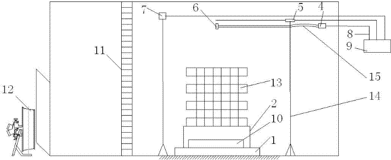
[0045] Example 1: The oil pan (containing 50L diesel oil) is placed on the high-temperature-resistant support 2, and the high-temperature-resistant support 2 is placed on the high-temperature-resistant floor scale 1. The bolometer is 0.5 m away from the oil pan in the horizontal direction, and the thermoelectric Couple 5 and bidirectional probe 6 are fixed 1 m directly above the oil pan through brackets. The bolometer, the thermocouple 5, the bidirectional probe 6, and the high temperature floor scale 1 transmit the data to the data acquisition system through the compensation wire 8.

[0046] When measuring, first start the data acquisition system, ignite the diesel oil, measure the quality change, temperature change, heat radiation amount change and fire plume flow pressure of the diesel oil over time, and obtain the combustion rate of the combustibles according to the measurement results kg / s, and then use the oxygen bomb calorimeter to measure the calorific value of the c...

Embodiment 2

[0054] To measure the influence of fire source power under windy conditions, the specific implementation method is as follows:

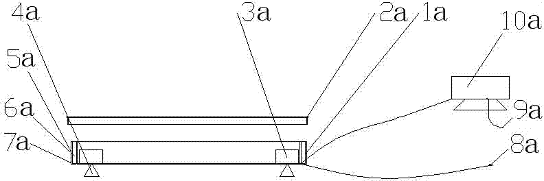
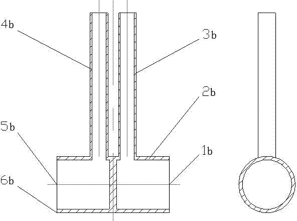
[0055] The wooden stack is placed on the high-temperature-resistant bracket, the high-temperature-resistant bracket is placed on the floor scale, the constant power ignition plate is placed directly under the wooden stack, and is located on the floor scale. The heat radiation meter is 0.5 meters away from the oil pan in the horizontal direction. The two-way probe 6 is fixed 1 meter directly above the oil pan through a bracket. The rectification grid is 1 meter away from the edge of the wood stack in the horizontal direction, and the blower is located behind the rectification grid and behind the opened door. The bolometer, thermocouple, and weighbridge transmit the data to the data acquisition system through the compensation wire. The bidirectional probe 6 is connected to the micromanometer through the trachea, and the micromanometer transmits the da...


PUM

PropertyMeasurementUnit
Calorific valueaaaaaaaaaa
Thermal poweraaaaaaaaaa

Abstract

The invention belongs to the technical field of fire control, and particularly relates to a device and a method for measuring combustion characteristics of combustible materials. The device consists of a high temperature resistant weighbridge, a high temperature resistant bracket, an oil pan, a micromanometer, a thermocouple, a two-way probe, a thermal radiometer, a compensating conductor, a dataacquisition system, an ignition pan, a rectification grid, an air feeder, a bracket and an air tube. The device is arranged in a fire experiment lab, combustible materials to be measured are arrangedon a tray of the weighbridge, after the combustible materials are ignited with the constant-power ignition pan, the air feeder is started, and the mass loss rate, the fireplume speed, the temperatureand the radiant heat of the combustible materials under different air speed are measured. Then combustion heat measured with an oxygen bomb calorimeter is multiplied by the combustion rate to obtain the thermal power of the combustible materials. The device has a simple structure, the calculation is convenient, the limitation of laboratory conditions and fire source power is small, and the deviceand the method are suitable for measuring the combustion characteristics of large combustible materials.

Description

technical field [0001] The invention belongs to the technical field of fire protection, and in particular relates to a device and method for measuring the mass loss rate of combustibles, fire plume velocity, radiant heat and thermal power. Background technique [0002] Fire source combustion rate, thermal power, radiant heat, and fire plume velocity are the main parameters of fire tests. The invention can quantitatively measure the combustion process of combustibles, collect measurement data in real time, and analyze its combustion properties. [0003] At present, the method of measuring the thermal power of combustibles in the world is mainly to use a cone calorimeter to calculate the thermal power by measuring the oxygen consumption and the composition of the flue gas. It has strict requirements on the laboratory and experimental conditions, and the calculation is complicated and expensive. The power of the fire source measured is small, and it is mainly used for fire rese...

Claims


Application Information

Patent Timeline
IPC IPC(8): G01N25/22
Inventor 苏琳王丽晶薛林王志辉田永祥张杰严攸高
Owner SHANGHAI FIRE RES INST OF MEM
Why Eureka
Try Eureka