Combination device for testing large current aging and vacuum degree of a vacuum arc extinguish chamber

A technology of vacuum interrupter and combination device, which is applied in the direction of high-voltage/high-current switches, circuits, electric switches, etc., can solve the problems of low production efficiency, high labor intensity of operators, and long operation time, so as to improve production efficiency, Effect of reducing labor intensity and working time, reducing labor intensity and working time

Active Publication Date: 2012-01-25
中国振华电子集团宇光电工有限公司(国营第七七一厂)
View PDF4 Cites 4 Cited by
  • Summary
  • Abstract
  • Description
  • Claims
  • Application Information

AI Technical Summary

Problems solved by technology

At present, the high-current burn-in and vacuum degree test of the vacuum interrupter need to be carried out on the burn-in bench and the test bench respectively, which not only takes a long time to operate, the production efficiency is low, and the labor intensity of the operators is relatively high

Method used


Image

  • Combination device for testing large current aging and vacuum degree of a vacuum arc extinguish chamber
  • Combination device for testing large current aging and vacuum degree of a vacuum arc extinguish chamber
  • Combination device for testing large current aging and vacuum degree of a vacuum arc extinguish chamber

Examples


Embodiment 1

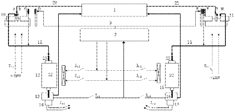
[0034] Example 1. Such as figure 1 As shown, it includes a high-current aging platform 1 and a magnetron vacuum gauge 2, with two stations, namely figure 1 No. 1 station 12 and No. 2 station 15 in. The aging switch of aging table 1 is respectively connected to No. 1 conversion cylinder 10 and No. 2 conversion cylinder 11, and the pneumatic switch of aging table 1 is respectively connected to clamping cylinder 13 and pull-down cylinder 14 of No. 1 station 12 and No. 2 station Clamping cylinder 16 and pull-down cylinder 17 of 15; A pair of conductive blocks A, B and another pair of conductive blocks C, D are housed on the No. 1 conversion cylinder 10, and a pair of conductive blocks E, F and D are housed on the No. 2 conversion cylinder 11. Another pair of conductive blocks G and H; conductive blocks A and C are connected to the aging clip line 18 of the first station 12, conductive blocks H and F are connected to the aging clip line 19 of the second station 15, and the conduc...

Embodiment 2

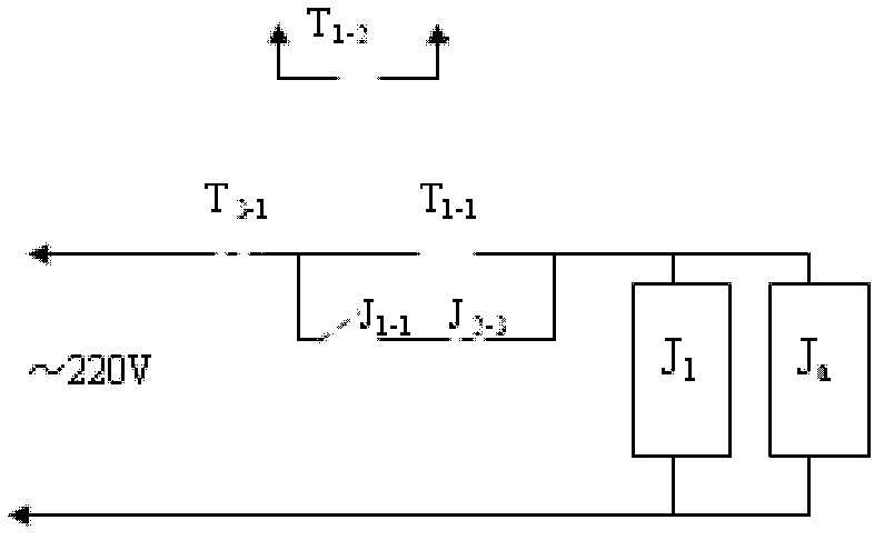
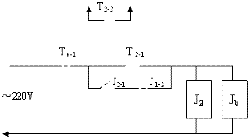
[0037] Example 2. Such as Figure 4As shown, it includes a high-current aging table 1 and a magnetron vacuum gauge 2. There is only one station 3, and a clamping cylinder 4 and a pull-down cylinder 5 are installed on the station 3. The aging switch of the aging table 1 is connected to the transfer cylinder 6, and the pneumatic switch of the aging table 1 is connected to the clamping cylinder 4 and the pull-down cylinder 5; a pair of conductive blocks A, B and another pair of conductive blocks C, D, conductive block A is connected to aging clip line 7, conductive block B is connected to aging table 1 through aging line 8, conductive block C is connected to aging clip line 7, conductive block D is connected to vacuum gauge 2 through high-voltage line 9; Gauge 2 respectively with AC contactor J a contact J a-1 , contact J a-2 and contact J a-4 connected. The burn-in switch adopts a self-locking switch with multiple sets of contacts, and the normally open contact T of the bu...


PUM


Abstract

The invention discloses a combination device for testing large current aging and vacuum degree of a vacuum arc extinguish chamber. An aging switch of an aging bench (1) is connected with a conversion cylinder (6); a pneumatic switch of the aging bench (1) is connected with a clamping cylinder (4) and a pull-down cylinder (5); a pair of conductive blocks A and B and another pair of conductive blocks C and D are arranged on the conversion cylinder (6); the conductive A is connected with an aging clip line (7); the conductive B is connected to the aging bench (1) through an aging line (8); the conductive C is connected with the aging clip line (7); the conductive D is connected to a vacuum gauge (2) through a high-voltage line (9); and the vacuum gauge (2) is connected with a contact Ja-1, acontact Ja-2 and a contact Ja-4 of an alternating current contactor Ja respectively. In the invention, test functions of large current aging and vacuum degree are combined, so the conductive blocks at a static end are prevented from being collided in an original test process, the labor intensity of an operator is reduced, the working time is shortened, and the production efficiency is improved.

Description

technical field [0001] The invention relates to a vacuum interrupter, in particular to a combined device for high-current aging and vacuum degree testing of the vacuum interrupter, which belongs to the technical field of electric appliances. Background technique [0002] Vacuum extinguishing chamber aging is to use DC low voltage and high current to arc and ablate the contact surface of the sealed arc extinguishing chamber to improve the withstand voltage and breaking capacity of the arc extinguishing chamber. The vacuum degree measuring instrument of vacuum interrupter is developed according to the principle of magnetron vacuum gauge, and its characteristic is to generate high voltage and receive tiny current. At present, the high-current burn-in and vacuum test of the vacuum interrupter need to be carried out on the burn-in bench and the test bench respectively, which not only requires long operation time, low production efficiency, but also high labor intensity for operat...

Claims


Application Information

Patent Timeline
Patent Type & Authority Applications(China)
IPC IPC(8): H01H33/668H01H11/00
Inventor 曾定勇杨杰蒋兴彪
Owner 中国振华电子集团宇光电工有限公司(国营第七七一厂)
Why Eureka
Try Eureka