
High-frequency automatic quenching machine for reverse gear shafts of transmission cases

A technology for reverse gear shafts and gearboxes, which is applied in the field of high-frequency automatic quenching machines for reverse gear shafts of gearboxes, and can solve problems such as low production efficiency, high labor intensity, and inability to adapt to large-scale and large-scale production of reverse gear shafts. , to achieve the effect of improving production efficiency and reducing labor intensity

Inactive Publication Date: 2012-02-01
ANHUI MINGYAN GEAR
View PDF8 Cites 15 Cited by
  • Summary
  • Abstract
  • Description
  • Claims
  • Application Information

AI Technical Summary

Problems solved by technology

In the current heat treatment process, most of them use ordinary medium and high frequency induction heating machine tools, which are carried out manually. Although the process has the characteristics of simple equipment, light weight and flexible operation, due to the manual operation method, it must be skilled. Operators, the labor intensity is high, the production efficiency is low, and it cannot meet the needs of large-scale and large-scale production of reverse gear shafts.
At the same time, due to the direct manual operation, the radiation of the induction heating equipment and the high-strength magnetic field have caused great harm to human health.

Method used


Image

  • High-frequency automatic quenching machine for reverse gear shafts of transmission cases
  • High-frequency automatic quenching machine for reverse gear shafts of transmission cases
  • High-frequency automatic quenching machine for reverse gear shafts of transmission cases

Examples


Embodiment Construction

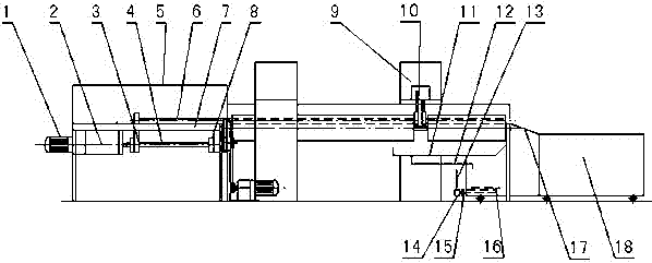
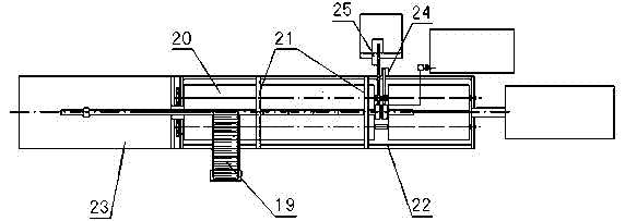
[0022] Such as figure 1 , 2 As shown, a gearbox reverse shaft high-frequency automatic quenching machine is composed of a pushing mechanism, an idler mechanism, an automatic feeding mechanism, a pressing frame mechanism, a heating power supply, a quenching and cooling device, a discharging mechanism and a PLC.

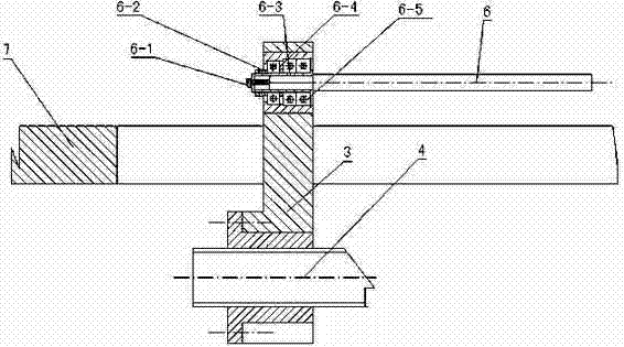
[0023] Pushing mechanism is made of pushing motor, gear box, nut seat, transmission screw mandrel, screw mandrel seat, pushing rod, upper cover plate 5 and pushing frame bed. Wherein, the pusher motor 1, transmission box 2, nut seat 3, transmission screw mandrel 4 and screw mandrel seat 8 are installed and connected to the bottom of the upper bed plate 7 of the pusher frame bed 23 in turn, and the top of the nut seat passes through the pusher frame The through groove opened in the middle of the upper bed board, the upper inner hole is equipped with a rotating sleeve 6-3 (see image 3 ), a plane bearing 6-4 and a bearing 6-5 are installed in the rotating sleeve, and a...


PUM


Abstract

The invention discloses a high-frequency automatic quenching machine for reverse gear shafts of transmission cases, which comprises a material pushing mechanism, a supporting roller mechanism, an automatic feeding mechanism, a material pressing rack mechanism, a heating power supply, a quenching liquid cooling device, an unloading mechanism and a PLC (programmable logic controller), wherein a through groove formed on a nut seat (3) on a transmission lead screw (4) of a material pushing motor (1) in the material pushing mechanism along a bed body of the material pushing rack can drive a material pushing rod (6) in a rotating sleeve (6-3) to push workpieces which are converted onto the supporting roller mechanism from the automatic feeding mechanism out of a working position between the roller surfaces of a left supporting roller (20-6) and a right supporting roller (20-7) one by one and mutually push the workpieces into an outer circular induction coil (10-1) in a heating power supply (9) for heating, then the workpieces enter a liquid spraying ring in the quenching liquid cooling device for performing liquid spraying and quenching, and the workpieces further enter a material barrel (18) through an unloading plate (17) after the workpieces are cooled. The high-frequency automatic quenching machine realizes the purpose of performing automatic heating and quenching on the workpieces, greatly reduces the labor intensity, improves the production efficiency, and is suitable for large-batch and large-scale production and processing of the reverse gear shafts of the transmission cases.

Description

technical field [0001] The invention relates to a high-frequency automatic quenching machine for a reverse gear shaft of a gearbox, which belongs to the technical field of processing machinery equipment. Background technique: [0002] During the use of the gearbox reverse gear shaft, surface wear is the main cause of failure. In the current heat treatment process, most of them adopt the induction heat treatment production process. Induction heat treatment is a process used for surface hardening. Its purpose is to pass through the induction coil with a certain frequency of alternating current, and the generated alternating magnetic field will generate a certain frequency of induced current (eddy current) in the workpiece, and use the resistance of the workpiece to heat the workpiece. Due to the skin effect of the induced current, the The surface layer of the workpiece is rapidly heated to austenitization, and then rapidly cooled immediately to obtain a hardened layer with a...

Claims


Application Information

Patent Timeline
Patent Type & Authority Applications(China)
IPC IPC(8): C21D1/10C21D1/667C21D9/28
CPCY02P10/25
Inventor 胡少名周向东
Owner ANHUI MINGYAN GEAR
Learn More