Construction method for pouring airtight partition wall between recovered roadway and reserved roadway

A construction method and partition wall technology, applied in tunnels, tunnel linings, mining devices, etc., can solve the problems of uneconomical, slow construction and high cost, and achieve high labor efficiency, fast construction and good airtightness.

Active Publication Date: 2012-02-01
XIAN UNIV OF SCI & TECH +1
View PDF4 Cites 26 Cited by
  • Summary
  • Abstract
  • Description
  • Claims
  • Application Information

AI Technical Summary

Problems solved by technology

The loess wall construction adopts manual feeding and manual compaction, and the sealing of the roof is poor. It needs to use special materials such as Marisan, Rock Hugh and other expansion materials to fill and seal the roof. The cost is high, uneconomical, and the construction speed is slow.
[0004] The sealing of rigid formwork concrete and its construction methods cannot meet the requirements of high-yield and high-efficiency mine recovery speed, which affects the normal production of the mine

Method used


Image

  • Construction method for pouring airtight partition wall between recovered roadway and reserved roadway
  • Construction method for pouring airtight partition wall between recovered roadway and reserved roadway
  • Construction method for pouring airtight partition wall between recovered roadway and reserved roadway

Examples


Embodiment 1

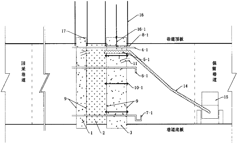
[0038] refer to Figure 1-10 A kind of construction method of pouring airtight partition wall between mining and reserved roadway, carry out according to the following steps:

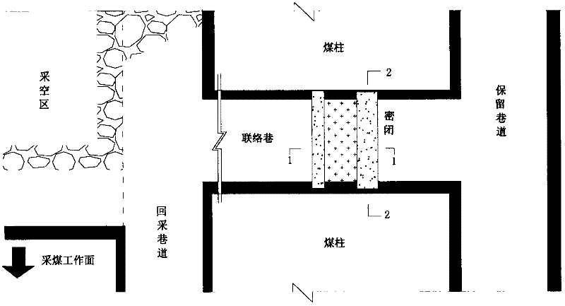
[0039] 1), the airtight partition wall is composed of concrete inner single wall 1, concrete outer single wall 3, and loess concrete middle wall 2;

[0040] 2), according to the size and function of the airtight partition wall, the flexible formwork 9 is prefabricated;

[0041] 3), excavate a cut 17 in the surrounding rock of the concrete inner single wall 1 and the outer single wall 3 to be set;

[0042] 4), drill bolt holes at the surrounding rock cutouts around the inner and outer concrete single walls, and install bolts 16 in the bolt holes;

[0043] 5), hang the prefabricated flexible formwork 9 on the anchor rod 16 or the single hydraulic prop 18, and inject concrete into the flexible formwork 9 through the concrete pump 15 through the concrete delivery pipe 14 and the pouring port 11 to form th...

Embodiment 2

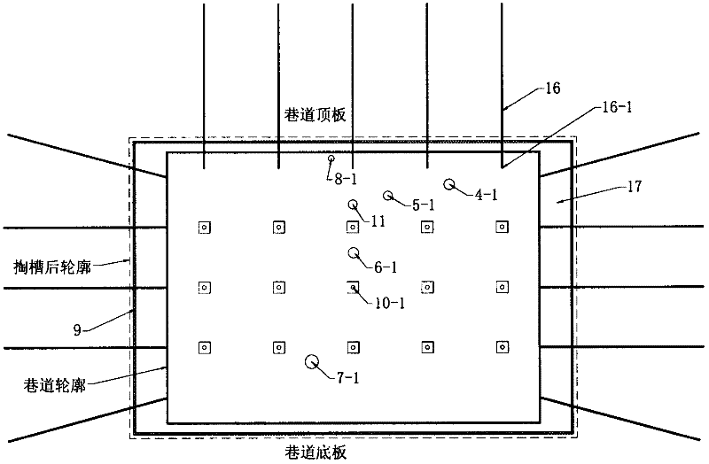
[0056] refer to Figure 5 , 2, 3, 7, 8, 9, 10: this airtight partition wall is made up of brick wall 1-1, concrete outer single wall 3 and middle loess concrete middle wall 2. The concrete outer single wall 3 has a groove 17 at the periphery of the roadway at the closed wall, and an anchor rod 16 is built in the groove, and the exposed end 16-1 of the anchor rod is inserted into the reinforcement opening 13, and the reinforcement opening 13 is bound by iron wire, and the anchor rod 16 The exposed end is bonded to the concrete in the flexible formwork 9, and the flexible formwork 9 is provided with flanges 12, anchor bolt holes 10, pouring ports 11, as well as measure pipe holes 4, observation pipe holes 6, and backwater pipe holes 7, etc. Holes, anchor bolt holes 10, measure pipe holes 4, observation pipe holes 6, and reverse water pipe holes 7 are respectively embedded with anchor bolts 10-1, measure pipes 4-1, observation pipes 6-1, and reverse water pipes 7-1. Between the...

Embodiment 3

[0059] refer to Figure 6 , 2 , 3, 7, 8, 9, and 10 show: a groove 17 is drawn around the roadway at the airtight partition wall, and an anchor rod 16 is built in the groove, and the exposed end 16-1 of the anchor rod penetrates the planting reinforcement port 13, and the planting reinforcement port 13 passes through Iron wire binding, the exposed end of the anchor rod 16 is bonded to the concrete in the flexible formwork 9, and the flexible formwork 9 is provided with a flange 12, an anchor bolt hole 10, a pouring port 11, and a measure pipe hole 4, an observation pipe hole 6, and a backwater pipe hole 7 and other closed holes are reserved, the anchor bolt hole 10, the measure pipe hole 4, the observation pipe hole 6, and the reverse water pipe hole 7 are respectively pre-buried anchor bolt 10-1, measure pipe 4-1, observation pipe 6-1, reverse water pipe hole 7, etc. Water pipe 7-1, such that the concrete airtight outer single wall 3 forms a concrete airtight partition wall. ...


PUM


Abstract

The invention discloses a construction method for pouring an airtight partition wall between a recovered roadway and a reserved roadway. The airtight partition wall is formed by an inner concrete single wall, an outer concrete single wall and a middle loess concrete wall; and the airtight structure is provided with three layers of walls: the inner side and the outer side are respectively provided with the airtight single wall which is formed in a way that a concrete pump pours concrete into a fiber flexible template, and the loess concrete wall filled by loess-based materials is arranged between the two single walls. The flexible templates are made in advance according to design requirements; a slot is drilled on a preset airtight surrounding rock connecting the roadways; anchor rods are constructed in the slot; after the flexible templates are hung onto the slot through a single hydraulic prop or the anchor rods, the concrete is successively poured into the inner side flexible template and the outer side flexible template by a concrete conveying pipe and a pouring opening through the concrete pump to form the inner single wall and the outer single wall; and after the inner single wall and the outer single wall are poured completely, the loess is poured between the inner single wall and the outer single wall to form the concrete airtight wall. The structure is safe and reliable, the construction cost is low, the construction speed is fast, the labor intensity is low, and the requirements of mine production with high production and high efficiency are met.

Description

technical field [0001] The invention relates to a mine airtight construction method, in particular to a construction method for pouring an airtight partition wall between mining and reserved roadways. Background technique [0002] Traditional mine closed cement concrete construction uses rigid formwork, such as steel formwork, wooden formwork, and plastic formwork. Manual feeding and manual vibration are used for concrete pouring, which requires a lot of manpower and material resources. The labor intensity is high, the construction speed is slow, and the cost is high; Moreover, the rigid formwork is not easy to change with the fluctuation of the slope surface of the roof and floor, resulting in poor airtightness, easy grout leakage during the pouring of concrete, and the poured concrete is not dense, it is difficult to be tightly combined with the coal seam roof, and it is easy to leak gas and water, which poses a threat to safety. Production poses hidden dangers. [0003] ...

Claims


Application Information

Patent Timeline
Patent Type & Authority Applications(China)
IPC IPC(8): E21D11/10E21F17/103
Inventor 王晓利吴玉意王大钊刘忠平
Owner XIAN UNIV OF SCI & TECH
Why Eureka
Try Eureka