Gradient ridge loading tortuous waveguide slow wave line

A meandering waveguide and meandering slow wave technology, applied in the field of traveling wave tube amplifiers, can solve the problems of no impedance matching, large reflection oscillation, uneven propagation path, etc.

Inactive Publication Date: 2012-02-01
UNIV OF ELECTRONICS SCI & TECH OF CHINA
View PDF6 Cites 8 Cited by
  • Summary
  • Abstract
  • Description
  • Claims
  • Application Information

AI Technical Summary

Problems solved by technology

However, due to the inhomogeneity introduced by the rectangular metal ridge 4 on the propagation path, and there is no effective impedance matching, the slow wave line of this structure generally has a large standing wave co

Method used


Image

  • Gradient ridge loading tortuous waveguide slow wave line
  • Gradient ridge loading tortuous waveguide slow wave line
  • Gradient ridge loading tortuous waveguide slow wave line

Examples


Embodiment Construction

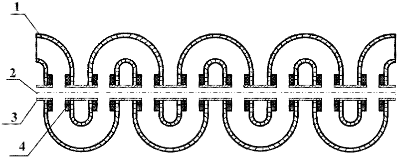
[0027] Such as Figure 7 with Figure 8 , in the 3mm wave band, the structural dimensions of the specific scheme of loading the meandering waveguide slow wave line with the linear gradient ridge are as follows: (unit: mm) a=2, b=0.3, H=0.6, L=1.542, r 0 =0.2, w=2, d=0.07, h 1 =0.42, h 2=0.09, h=H=0.6. Use three-dimensional electromagnetic simulation software to simulate the slow-wave structure of the gradient ridge loading meander waveguide provided by the present invention, obtain its dispersion characteristics, coupling impedance, standing wave coefficient and high-frequency loss, and have the same ridge width w, the same ridge overall height h is compared with the ridge-loaded meander waveguide slow-wave structure with the same ridge thickness d. The three-dimensional electromagnetic simulation software is used to simulate the two slow wave structures for 40 cycles respectively, and obtain the standing wave coefficient and S parameter of the two structures. Simulation ...


PUM


Abstract

The invention discloses a gradient ridge loading tortuous waveguide slow wave line, and belongs to the technical field of microwave vacuum electronics. The slow wave line is formed by alternately connecting a series of arc bent waveguides (or right-angled bent waveguides) and straight waveguides end to end, equivalently a rectangular waveguide (1) is periodically bent into a tortuous waveguide structure along an electric field surface. A gradient metal ridge sheet (4) is loaded on the inner wall of the straight waveguide of each tortuous unit; and a circular through hole is formed in a middle axis symmetric line (2) on the waveguide wall and the metal ridge sheet along the slow wave structure, and the circular through holes of the straight waveguides of the two adjacent tortuous units are connected by adopting a metal pipe (3) with the same size as the apertures of the circular through holes to form an electron injection channel. When relatively high coupling impedance of the ridge loading tortuous waveguide slow wave line is kept, the standing wave coefficient of the ridge loading tortuous waveguide slow wave line can be reduced, and the transmission property of the slow wave line is improved; and the reflecting oscillation of a ridge loading tortuous waveguide traveling wave tube is inhibited, so that the ridge loading tortuous waveguide traveling wave tube has higher gain and efficiency.

Description

technical field [0001] The invention belongs to the technical field of microwave vacuum electronics, and relates to a traveling wave tube amplifier. Background technique [0002] Traveling wave tubes have the incomparable advantages of broadband, high gain and low noise, etc., which are incomparable to other electric vacuum devices. They have strong vitality and have been widely used in microwave frequency bands. As the core component of the TWT, the slow wave line directly affects the efficiency of the beam-wave interaction and the technical level of the entire TWT. Helix and coupled cavity are the two most commonly used slow wave lines in traveling wave tubes. The helical TWT has a very wide frequency range. With the development of technology and materials, and the improvement of manufacturing technology, its power level has been further improved. However, due to the small heat capacity and low dissipation capacity, the improvement of the output power of the helical TWT ...

Claims


Application Information

Patent Timeline
IPC IPC(8): H01J23/24
Inventor 魏彦玉郭彍岳玲娜赵国庆段兆云宫玉彬王文祥
Owner UNIV OF ELECTRONICS SCI & TECH OF CHINA
Why Eureka
Try Eureka