Direct-current brushless motor and drainage pump

A brushless DC motor and motor shaft technology, which is applied in the direction of pumps, electrical components, electromechanical devices, etc., can solve the problems of high machining accuracy of stator core, reducing the accuracy of stator core thickness, and degraded motor performance. Achieve the effect of small vibration, improve position accuracy, and improve control accuracy

Inactive Publication Date: 2012-02-08
ZHEJIANG SANHUA INTELLIGENT CONTROLS CO LTD
View PDF5 Cites 11 Cited by
  • Summary
  • Abstract
  • Description
  • Claims
  • Application Information

AI Technical Summary

Problems solved by technology

[0006] However, the brushless DC motor with the above structure has certain defects: the hole on the stator core is used for positioning between the upper end cover and the lower end cover of the motor, and the coaxiality between the two end covers depends on the machining accuracy of the stator core. The centrality and dimensional accuracy of the hole, the dimensional accuracy of the boss of the end cover, the coaxiality of the bearing and the end cover, the above factors comprehensively affect the coaxi

Method used


Image

  • Direct-current brushless motor and drainage pump
  • Direct-current brushless motor and drainage pump
  • Direct-current brushless motor and drainage pump

Examples


Example Embodiment

[0034] In order to make the objectives, technical solutions, and advantages of the embodiments of the present invention clearer, the technical solutions in the embodiments of the present invention will be described clearly and completely in conjunction with the accompanying drawings in the embodiments of the present invention. Obviously, the described embodiments It is a part of the embodiments of the present invention, not all the embodiments. Based on the embodiments of the present invention, all other embodiments obtained by those of ordinary skill in the art without creative work shall fall within the protection scope of the present invention.
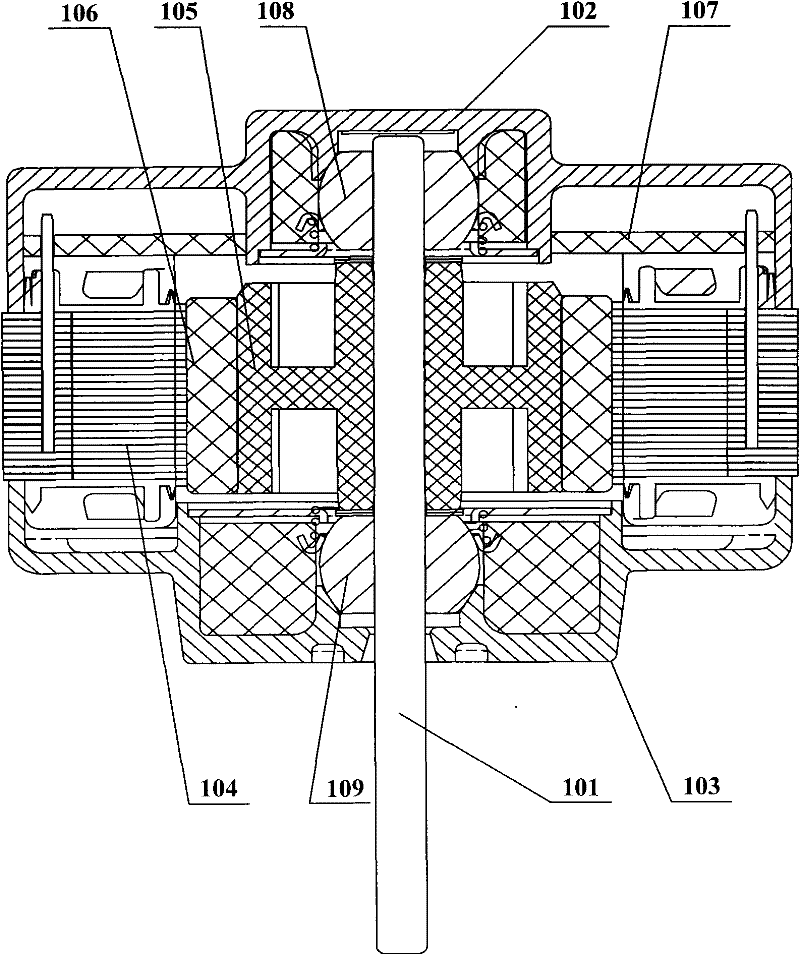
[0035] Figure 4 This is a schematic cross-sectional structure diagram of a brushless DC motor provided by an embodiment of the present invention. The basic components of the brushless DC motor include an upper end cover 102, a lower end cover 103, a motor shaft 101, a stator assembly 104, and a rotor magnet 106. The motor The shaft 1...


PUM


Abstract

The invention discloses a direct-current brushless motor and a drainage pump. The direct-current brushless motor comprises: an upper end cover, a lower end cover, a motor shaft, a stator assembly and a rotor magnet steel. The motor shaft is arranged through the upper end cover and the lower end cover. The rotor magnet steel is sleeved on an outside of the motor shaft. Outside edges of the upper end cover and the lower end cover are mutually fastened. Outer positioning structures which form mutual cooperation are respectively formed on the edges of the upper end cover and the lower end cover. The stator assembly is arranged in a cavity which is formed by fastening of the upper end cover and the lower end cover. Mutually cooperated inner positioning structures are formed on outer walls of the stator assembly and inner walls of the cavity. In the invention, the upper end cover and the lower end cover are directly fastened and positioned; the stator assembly is fixed in the end cover so that coaxiality of the stator and the rotor of the motor can be raised and position precision of the stator in the end cover can also be raised. Control precision of axial clearance and radial clearance can be improved. Uniformity of an electromagnetic air gap is good. Therefore, operation of the motor is stable, noise is low and vibration is small.

Description

technical field [0001] Embodiments of the present invention relate to motor structure technology, in particular to a DC brushless motor and a drainage pump. Background technique [0002] Drainage pumps are widely used in drainage equipment in various fields of production and life. For example, the indoor unit of a ceiling-mounted air conditioner needs to use a drain pump. When the air conditioner is running, a large amount of condensed water will be generated on the surface of the heat exchanger due to the cooling of the air. When the water accumulates to a certain extent, it will drop into the condensed water tank below the heat exchanger. It is necessary to install a drain pump inside to discharge the condensed water to the outside. Usually, according to different application requirements, the drainage pump is required to have a certain flow rate and head, and due to the noise requirements of the use environment, the working noise of the drainage pump should also be limi...

Claims


Application Information

Patent Timeline
IPC IPC(8): H02K29/00H02K5/04H02K5/24F04B17/03
Inventor 赵剑锋
Owner ZHEJIANG SANHUA INTELLIGENT CONTROLS CO LTD
Why Eureka
Try Eureka