

Digitalized control method and device for pulse power source
A technology of pulse power supply and control method, which is applied in the direction of electric pulse generator circuit and active components to generate pulses, etc., can solve the problems of low integration and achieve the effect of improving performance
- Summary
- Abstract
- Description
- Claims
- Application Information
AI Technical Summary
Problems solved by technology
Method used
Image

Examples
Embodiment 1
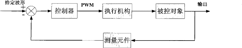
[0032] Arbitrary waveform pulse power requires a controller with fast response time and high tracking accuracy for a given waveform.
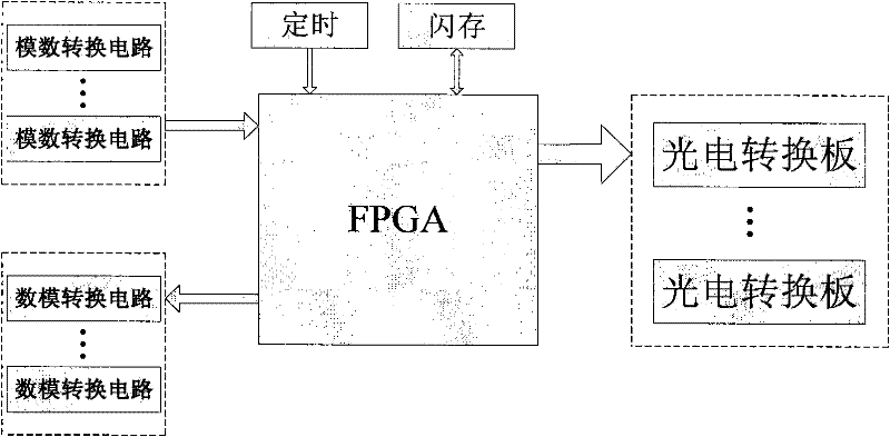
[0033] The mainstream products of FPGA are VIRTEX-6 (high-performance series) and SPARTAN-6 (low-cost series) of XILINX Company, Stratix-IV (high-performance series) and Cyclone-IV (low-cost series) of ALTERA Company. Among the present invention, FPGA adopts Cyclone-II series product of ALTERA company, and Cyclone II device provides 4,608 to 68,416 logic elements (LE), and has a whole set of best functions, including embedded 18-bit x18-bit multiplier, special-purpose external memory Interface circuit, 4kbit embedded memory block, phase-locked loop (PLL) and high-speed differential I / O capability. Cyclone-II series product has EP2C5, EP2C8, EP2C15, EP2C20, EP2C35, EP2C50, EP2C70, how many internal resources are different, according to the control method of the present invention, FPGA adopts EP2C35F672, and it is FBGA package, totally 672 pins, ...
Embodiment 2
[0040] refer to Figure 4 , is a schematic diagram of the main circuit of the power supply controlled by the digital controller of the pulse power supply provided by the present invention. In the second embodiment, the main circuit structure of the arbitrary waveform pulse power supply is an IGBT topology in which m=5 IGBTH bridges are connected in series to form a unit, and n=10 units are connected in parallel. Figure 5 Shown is an enlarged view of the series structure of 5 IGBT H-bridges in each parallel unit in the main circuit of the power supply.
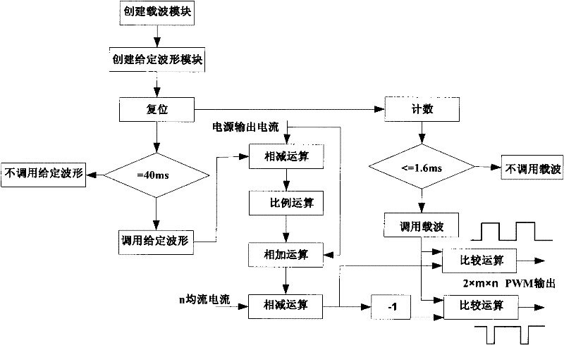
[0041] Refer again Figure 6 , for control Figure 4 The digital controller component layout diagram of the main circuit of the pulse power supply shown. The main circuit of the power supply with the above structure has 50 IGBT H-bridges, that is, 100 IGBT gates need to be controlled. Therefore, the digital controller must generate 2×m×n=100 PWM signals.
[0042] combine Figure 4 and Figure 6 , Figure 4 The output si...
PUM
 Abstract
Description
Claims
Application Information