
Spectrum scaling apparatus used for spectrum imager

A spectral imager and spectral calibration technology, which is applied in the field of uniform surface light sources, and can solve the problems of increasing the complexity and time of calibration, reducing the calibration period, and the output field of view and small aperture of the monochromator.

Inactive Publication Date: 2012-02-15
SUZHOU UNIV +1
View PDF3 Cites 30 Cited by
  • Summary
  • Abstract
  • Description
  • Claims
  • Application Information

AI Technical Summary

Problems solved by technology

[0003] The main problems of using a monochromator as a spectral calibration are: (1) only one monochromatic light can be output at a time, and it takes a long period to perform spectral calibration in the entire spectral range; (2) the monochromator’s The output field of view and aperture are small, and the uniformity is poor, which cannot directly meet the calibration requirements of large-field and large-aperture spectral imagers. It is necessary to design a special beam expansion and collimation optical system
[0004] When the excitation light source is used for spectral calibration, multiple excitation spectral lines can be collected at one time, but the existing problems are: (1) The excited spectral lines can only cover a few spectral segments of the spectral imager to be tested channel, when calibrating other channels, multiple excitation light sources are required to be used alternately, which increases the complexity and time of calibration; The center position and bandwidth of the center are interpolated by fitting calculations, and the calibration accuracy is poor
[0005] In order to ensure the calibration accuracy of the spectral imager and reduce the calibration cycle at the same time, how to provide a light source with a continuous narrow passband that varies with wavelength in a wide range of wavelengths, so that only a single acquisition can be achieved , the spectral calibration of the spectral imager can be realized. At present, the related technology has not been reported

Method used


Image

  • Spectrum scaling apparatus used for spectrum imager
  • Spectrum scaling apparatus used for spectrum imager
  • Spectrum scaling apparatus used for spectrum imager

Examples


Embodiment 1

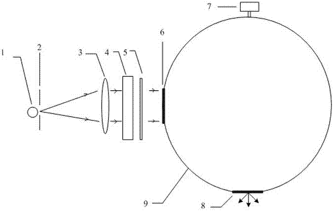
[0022] See attached figure 1 , which is a structural schematic diagram of a spectral calibration device for a spectral imager provided in this embodiment; the light beam emitted by the broadband light source 1 passes through the diaphragm 2 and the collimating lens 3, and then irradiates the wavelength tuning filter 4 On the top, the optical filter 4 adjusts the light transmittance of light of different wavelengths to generate a plurality of narrow-band optical signals distributed in a comb shape. 6 enters the integrating sphere 9 for depolarization and spatial uniformity processing, and the spectral imager to be tested is placed at the exit aperture 8 of the integrating sphere for spectral calibration.


PUM

PropertyMeasurementUnit
Thicknessaaaaaaaaaa

Abstract

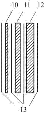
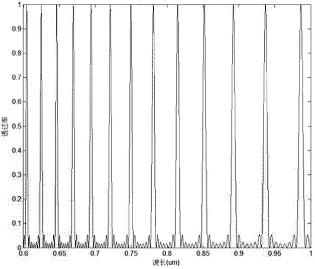
The invention discloses a spectrum scaling apparatus used for a spectrum imager. The apparatus is characterized in that: a light beam which is emitted by a broadband light source (1) goes through a diaphragm (2) and a collimating lens (3) and irradiates a wavelength tuning optical filter (4), a plurality of narrowband optical signals which are distributed in a comb-shaped mode and have different wavelengths are outputted, after light intensity adjusting by a broadband bandpass optical filter (5), the signals enter into an integrating sphere (9) from an integrating sphere incident light hole (6) for depolarization and space uniformity processing, and an integrating sphere light extraction hole (8) outputs a surface light source. A spectrum imager to be measured is placed on the light extraction hole (8) for spectrum scaling. According to the apparatus, a birefringence crystal is utilized to carry out light transmission rate modulation, a passband peak value position and a bandwidth size can be adjusted, a plurality of narrowband light intensity signals changing with a wavelength are provided in a broadband range, wavelength scanning is not needed when carrying out spectrum scaling on the spectrum imager, wavelength scaling with one-time imaging is realized, and the apparatus is suitable for scaling a large field of view and large caliber spectrum imager.

Description

Technical field [0001] The present invention involves a spectral setting device used to spectrum imaging instruments, and specially involves a uniform surface light source that can be emphasized by lighting. It has the characteristics of combing light distribution with the wavelength change. technical background [0002] The spectrum imaginger is a combination of "imaging" and "spectral" technology. It can identify the physical and chemical characteristics of objects. It is widely used in various aspects such as mineral development, environmental governance, forest fire prevention, agricultural production evaluation, and military detection.The premise of the spectrum imaging instrument is to provide the spectral curve of the real and reliable detected object, thereby a precise labeling of the spectrum imaginger.Among them, spectral standards are the setting of the center position and bandwidth of each spectrum segment, which is the basis for the application of spectrum imaging in...

Claims


Application Information

Patent Timeline
IPC IPC(8): G01J3/00G01J3/10G01J3/14G02B27/28G02B27/09
Inventor 周建康陈新华贺虎成陈宇恒季轶群沈为民
Owner SUZHOU UNIV
Learn More