Electric leakage protection plug
A leakage protection plug and resistor technology, applied in emergency protection circuit devices, automatic disconnection emergency protection devices, circuits, etc., can solve problems such as no grounding and electric shock accidents
- Summary
- Abstract
- Description
- Claims
- Application Information
AI Technical Summary
Problems solved by technology
Method used
Image
Examples
Embodiment 1
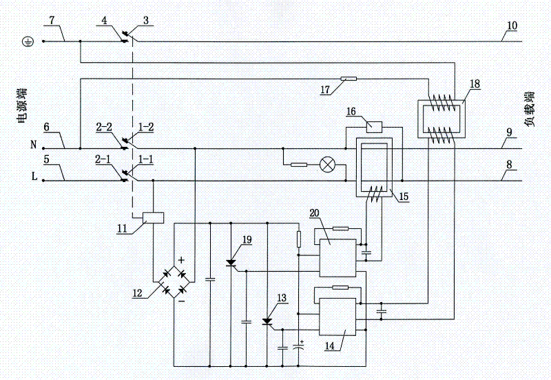
[0030] see figure 1 As shown, a leakage protection plug is mainly composed of a plug shell and a three-pole pin of phase, zero, and ground, a phase line 5, a neutral line 6, and a ground line 7 at the power supply end, a rectifier circuit 12, a first thyristor 19, and a second thyristor. SCR 13, first amplifying circuit 14, second amplifying circuit 20, zero-sequence current transformer 15, test circuit 16, weak current detection sensor 18, current-limiting resistance-capacitance element 17, load-side phase line 8, neutral line 9 , Ground wire 10, electromagnetic tripping and locking device. The electromagnetic tripping and locking device is mainly composed of electromagnetic coil 11 and its drive circuit, phase line contacts 1-1 and 2-1, neutral line contacts 1-2 and 2-2, ground line contacts 3 and 4, springs , Reset push rod composition. The primary winding of the weak current detection inductor 18 is connected in series with the current-limiting resistance-capacitance ele...
Embodiment 2
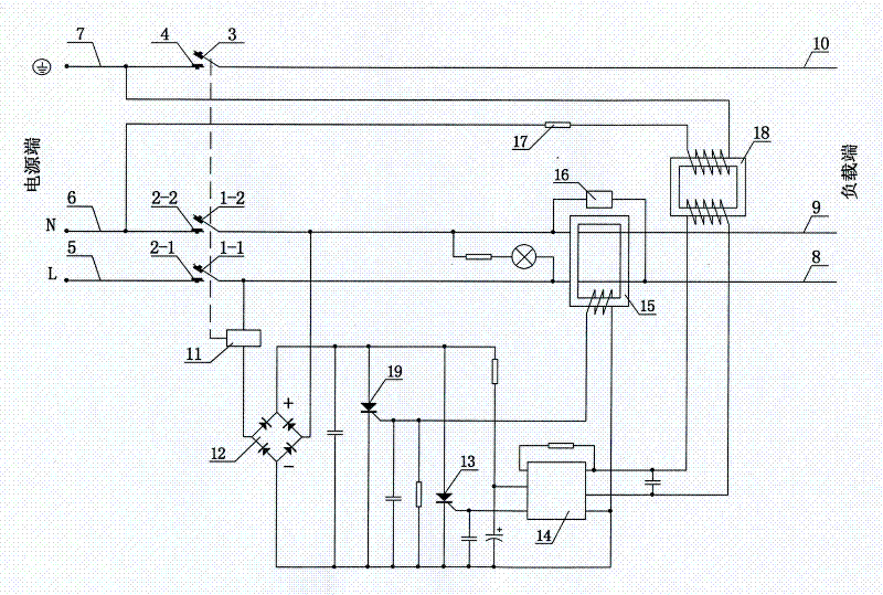
[0038] see figure 2 As shown, compared with Embodiment 1, this embodiment cancels the second amplifying circuit 20 described in Embodiment 1 in the driving circuit of the electromagnetic coil, and the output terminals of the secondary winding of the zero-sequence current transformer 15 are respectively and The parallel connection of the input terminal of the second amplifying circuit 20 described in Embodiment 1 is changed to be respectively connected in parallel with the trigger pole and cathode of the first thyristor 19 of this embodiment, and the anode and cathode of the first thyristor 19 are respectively connected to the rectifier circuit 12 The positive pole of the output terminal is connected to the negative pole, so that the signal output by the secondary winding of the zero-sequence current transformer 15 directly triggers the first thyristor 19. Since the signal output by the secondary winding of the zero-sequence current transformer 15 is large enough, it does not n...
Embodiment 3
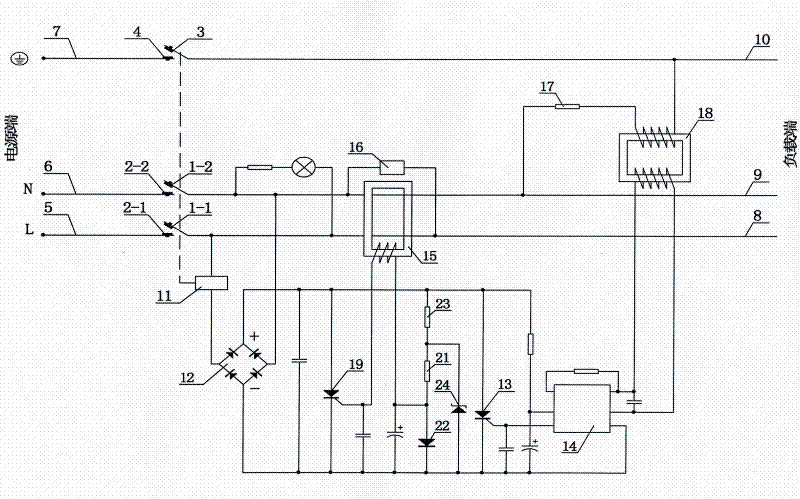
[0044] see image 3 As shown, compared with Embodiment 2, this embodiment adds a clamping diode 22 composed of a first resistor 23, a second resistor 21, a clamping diode 22, and a Zener diode 24 in the driving circuit of the electromagnetic coil. Positive clamp circuit. The clamping diode 22 is connected in series with the second resistor 21 and the first resistor 23 between the positive pole and the negative pole of the output terminal of the rectifier circuit 12, one end of the first resistor 23 is connected to the positive pole of the output terminal of the rectifier circuit 12, and the other end of the first resistor 23 is connected to the positive pole of the output terminal of the rectifier circuit 12. One end of the second resistor 21 is connected, the other end of the second resistor 21 is connected to the positive pole of the clamping diode 22, the negative pole of the clamping diode 22 is connected to the negative pole of the output terminal of the rectifier circuit...
PUM
 Abstract
Description
Claims
Application Information
 - R&D
- Intellectual Property
- Life Sciences
- Materials
- Tech Scout
- Unparalleled Data Quality
- Higher Quality Content
- 60% Fewer Hallucinations
Browse by: Latest US Patents, China's latest patents, Technical Efficacy Thesaurus, Application Domain, Technology Topic, Popular Technical Reports.
© 2025 PatSnap. All rights reserved.Legal|Privacy policy|Modern Slavery Act Transparency Statement|Sitemap|About US| Contact US: help@patsnap.com


