Rotary motor using composite bending vibration biped linear ultrasonic oscillators

A linear ultrasonic and rotary motor technology, applied in piezoelectric effect/electrostrictive or magnetostrictive motors, generators/motors, electrical components, etc., can solve the problems of low coupling efficiency and difficult to improve mechanical output capability, etc. Achieve the effect of high electromechanical coupling efficiency, improving electromechanical coupling efficiency and stable performance

Active Publication Date: 2012-02-15
HARBIN INST OF TECH
View PDF4 Cites 6 Cited by
  • Summary
  • Abstract
  • Description
  • Claims
  • Application Information

AI Technical Summary

Problems solved by technology

[0004] The purpose of the present invention is to solve the problems of low coupling efficiency and difficulty in improving the mechanical output capacity of the existing patch-type rotary piezoelectric ultrasonic motor, and to provide a rotary motor using a composite bending-vibration biped linear ultrasonic vibrator

Method used


Image

  • Rotary motor using composite bending vibration biped linear ultrasonic oscillators
  • Rotary motor using composite bending vibration biped linear ultrasonic oscillators
  • Rotary motor using composite bending vibration biped linear ultrasonic oscillators

Examples


specific Embodiment approach 1

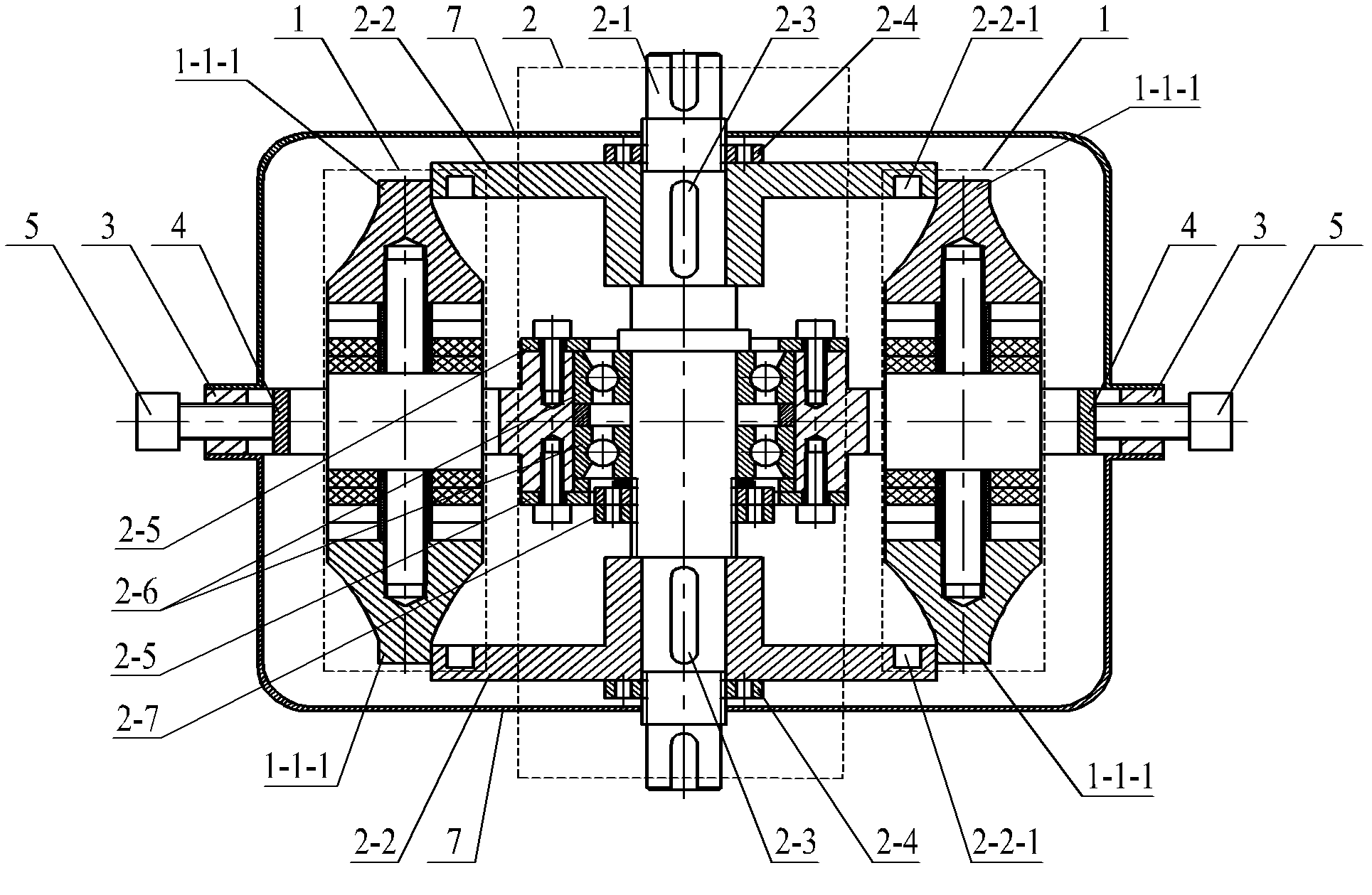
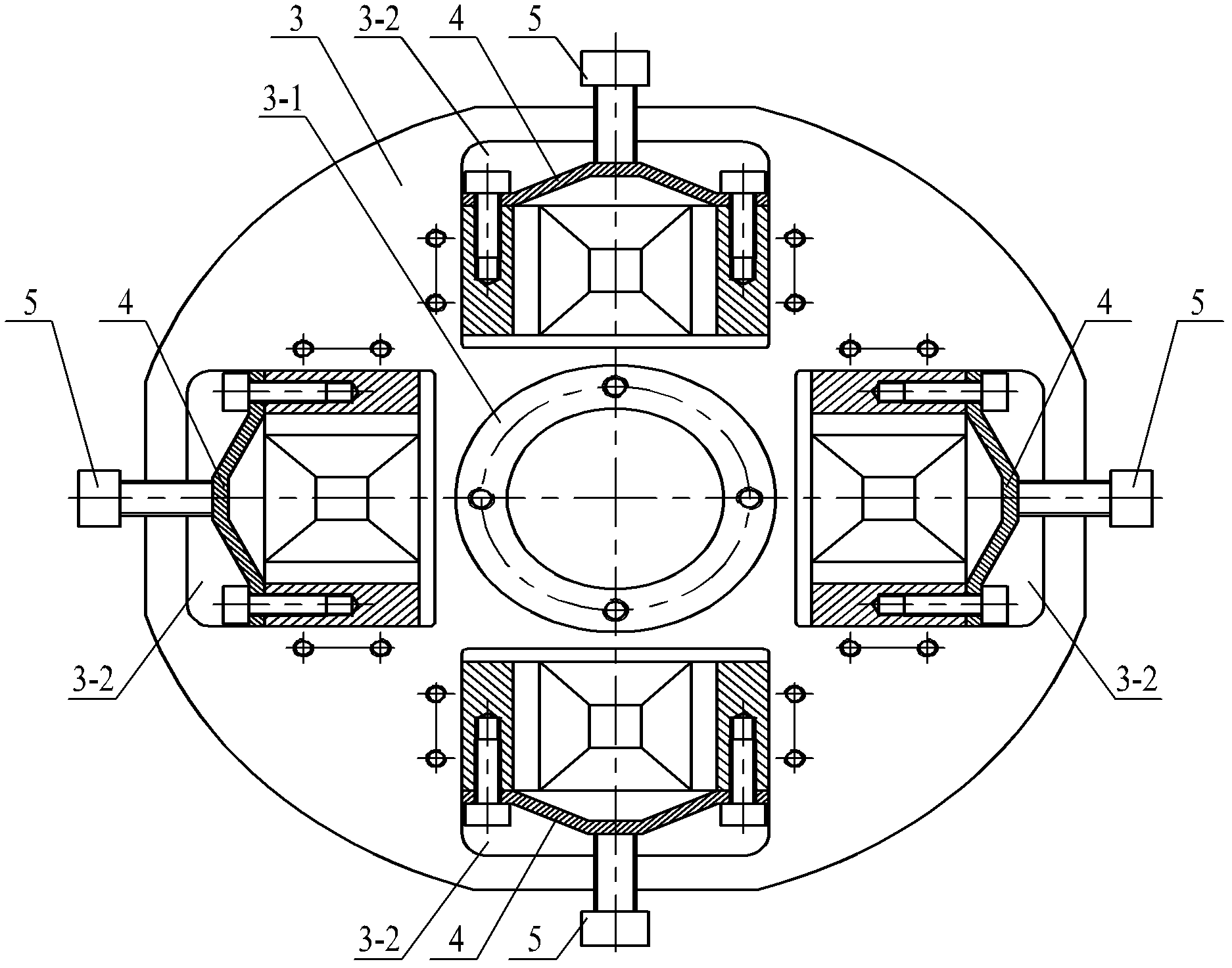
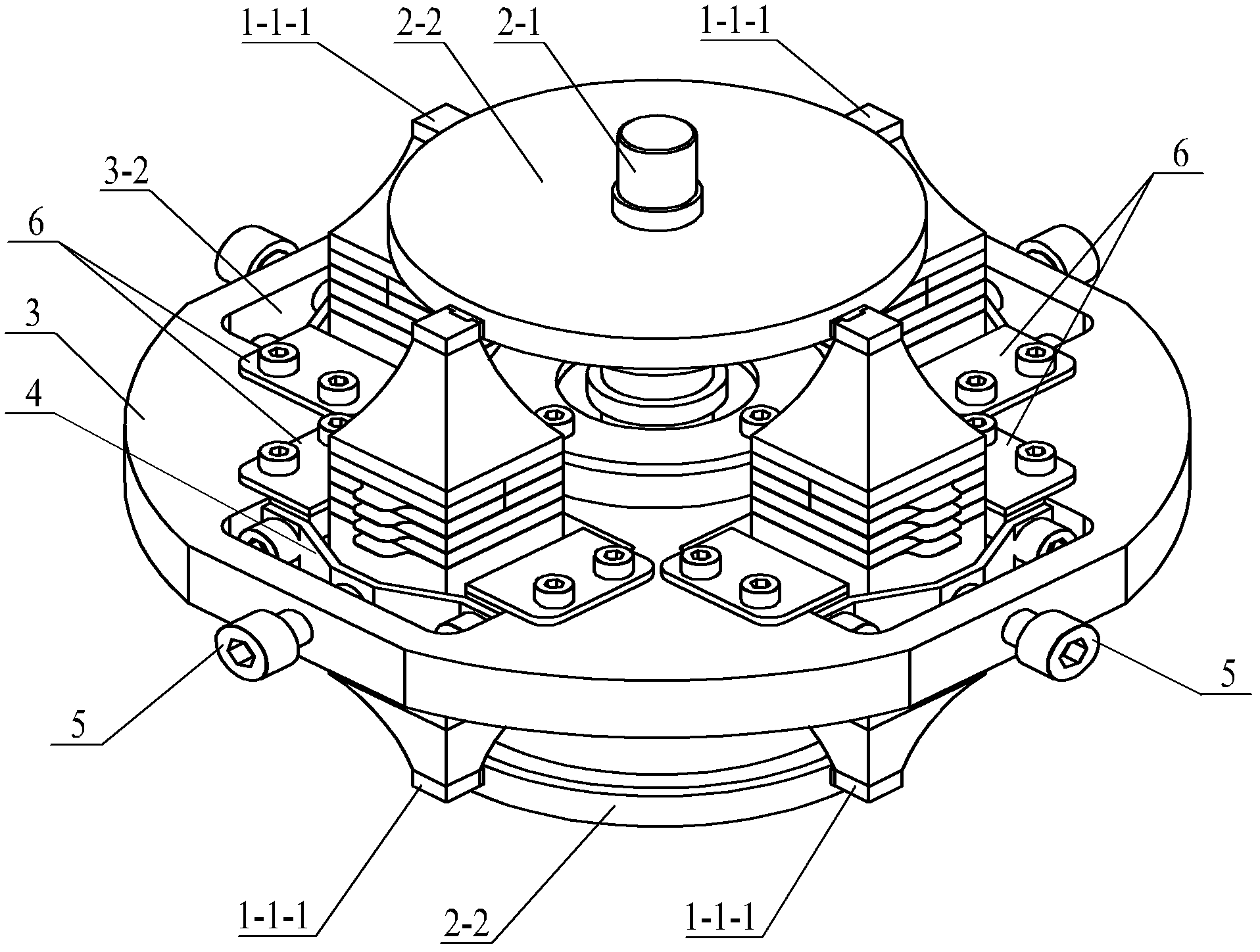
[0032] Specific implementation mode one: the following combination Figure 1 to Figure 8 Describe this embodiment, the rotary motor using the compound bending vibration biped linear ultrasonic vibrator described in this embodiment, it includes n vibrators 1, rotor assembly 2, base 3, n leaf springs 4, n preloading screws 5 and 4n baffles 6, n is a positive integer,

[0033] The center of the base 3 has a central through hole and is provided with a bearing seat 3-1, the rotor assembly 2 is arranged in the central through hole, and n rectangular sections are evenly distributed on the base 3 along the outer circumference direction of the bearing seat 3-1. Slot 3-2, a vibrator 1 is arranged in each rectangular section slot 3-2;

[0034] The rotor assembly 2 consists of a rotor shaft 2-1, two disc rotors 2-2, two coupling keys 2-3, two rotor lock nuts 2-4, two bearing end covers 2-5, two bearings 2 -6 and bearing preload nut 2-7,

[0035] The rotor shaft 2-1 passes through the c...

specific Embodiment approach 2

[0040] Specific implementation mode two: the following combination Figure 4 , Figure 5 and Figure 6 Describe this embodiment. This embodiment is a further description of Embodiment 1. The vibrator 1 in this embodiment includes two end covers 1-1, eight bending piezoelectric ceramic sheets 1-2, and flanges 1-3. , two thin-walled beams 1-4, two insulating sleeves 1-6, eight electrode sheets 1-7 and two friction sheets 1-8,

[0041] Two thin-walled beams 1-4 are symmetrically arranged in the middle of both sides of the flange 1-3, one end of each thin-walled beam 1-4 is fixedly connected to the side wall of the flange 1-3, and the other end of the thin-walled beam 1-4 is connected to a mounting seat 1-5 fixed connections,

[0042] A stud 1-3-1 is set in the center of the two end faces of the flange 1-3, and each stud 1-3-1 is covered with four pieces of bending vibration piezoelectric ceramic sheets 1-2, and the stud 1-3-1 An insulating sleeve 1-6 is arranged between 3-1 a...

specific Embodiment approach 3

[0048] Specific implementation mode three: the following combination Figure 4 , Figure 5 and Figure 6 Describe this embodiment, this embodiment is a further description of Embodiment 1 or 2, the rotating electrical machine in this embodiment also includes two outer covers 7,

[0049] The two outer covers 7 are symmetrically covered on the upper surface and the lower surface of the base 3 , and the end of the rotor shaft 2 - 1 passes through the center of each outer cover 7 .

[0050] The outer cover 7 is used to realize the packaging and protection of the rotating electrical machine.


PUM


Abstract

The invention provides a rotary motor using composite bending vibration biped linear ultrasonic oscillators, belonging to the technical field of piezoelectric ultrasonic motors. The invention solves the problems that the existing patch type rotary piezoelectric ultrasonic motor has low coupling efficiency, and the mechanical output capability is difficult to improve. The rotary motor provided by the invention comprises n oscillators, a rotor assembly, a base, n plate springs, n pre-pressing screws and 4n baffle plates, wherein n is a positive integer; the center of the base is provided with a central through hole and a bearing seat; the rotor assembly is arranged in the central through hole; n rectangular section slots are uniformly distributed on the base along the outer circumference direction of the bearing seat; one oscillator is arranged in each rectangular section slot; one plate spring is also arranged in each rectangular section slot; and the two ends of each plate spring are respectively connected fixedly with two installing seats of the oscillator positioned in the rectangular section slot. The rotary motor provided by the invention can realize large-torque output.

Description

technical field [0001] The invention relates to a rotating motor using a composite bending-vibration biped linear ultrasonic vibrator, belonging to the technical field of piezoelectric ultrasonic motors. Background technique [0002] Piezoelectric ultrasonic motor uses the inverse piezoelectric effect of piezoelectric ceramics to excite vibration in the ultrasonic frequency band in the elastic body, and forms a particle motion with a specific trajectory at a specific point or area on the surface of the elastic body, and then passes between the stator and the rotor. The friction coupling converts the microscopic motion of the particle into the macroscopic motion of the rotor. The piezoelectric ultrasonic motor has the advantages of low speed and high torque, no need for a speed change mechanism, no electromagnetic interference, fast response, and self-locking when power is off. [0003] Due to the simplicity of the excitation principle and the simplicity of the theoretical an...

Claims


Application Information

Patent Timeline
Patent Type & Authority Applications(China)
IPC IPC(8): H02N2/10
Inventor 刘英想陈维山刘军考石胜君
Owner HARBIN INST OF TECH
Why Eureka
Try Eureka