Cleaning and disinfection apparatus

A technology for cleaning and disinfecting tanks, applied in disinfection, tableware washing machines/rinsing machines, cleaning equipment, etc., can solve the problems of discounted sterilization effect, no protection device, poor cleaning effect, etc., achieve high efficiency and eliminate safety problems , Improve the effect of cleaning and disinfection efficiency

Inactive Publication Date: 2012-02-22
BEIJING YADU ENVIRONMENTAL PROTECTION TECH
View PDF15 Cites 27 Cited by
  • Summary
  • Abstract
  • Description
  • Claims
  • Application Information

AI Technical Summary

Problems solved by technology

[0009] (3) Most of the existing washing machines use floating mechanism water level controllers, which are easily disturbed by sundries, and some washing machines do not even have water level control devices, and rely solely on the user's naked eyes to control the water level. Water overflow, which will lead to safety problems such as electrical components being soaked in water
[0010] (4) In the existing cleaning device, the direct contact between the electrode and the water makes the water body electrified, and there is no protection device, which will cause a safety accident during use;
[0011] (5) In the existing ultrasonic cleaning device, the ultrasonic generator is placed at the bottom of the cleaning tank. When the amount of objects to be cleaned is large or the objects to be cleaned are piled up on each other or stacked, the ultrasonic cleaning will clean the objects stacked in the middle and upper layers. The effect is very poor;
[0012] (6) The use of ultraviolet rays in existing cleaning devices is mostly arranged at the bottom of the cleaning tank, and ultraviolet rays will rapidly attenuate in high-turbidity water, which greatly reduces the bactericidal effect; and when this type of cleaning device is used, it does not distinguish between Cleaning the object will cause organic matter to be destroyed during cleaning

Method used


Image

  • Cleaning and disinfection apparatus
  • Cleaning and disinfection apparatus

Examples


Embodiment Construction

[0031] In order to have a clearer understanding of the technical features, purposes and effects of the present invention, the specific implementation manners of the present invention will now be described with reference to the accompanying drawings.

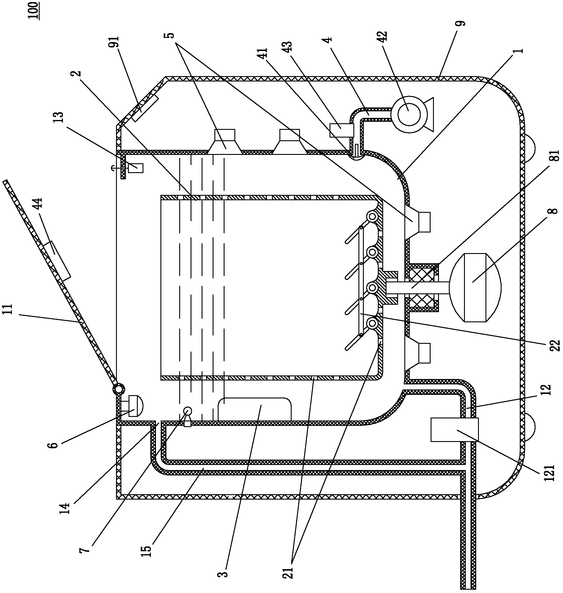
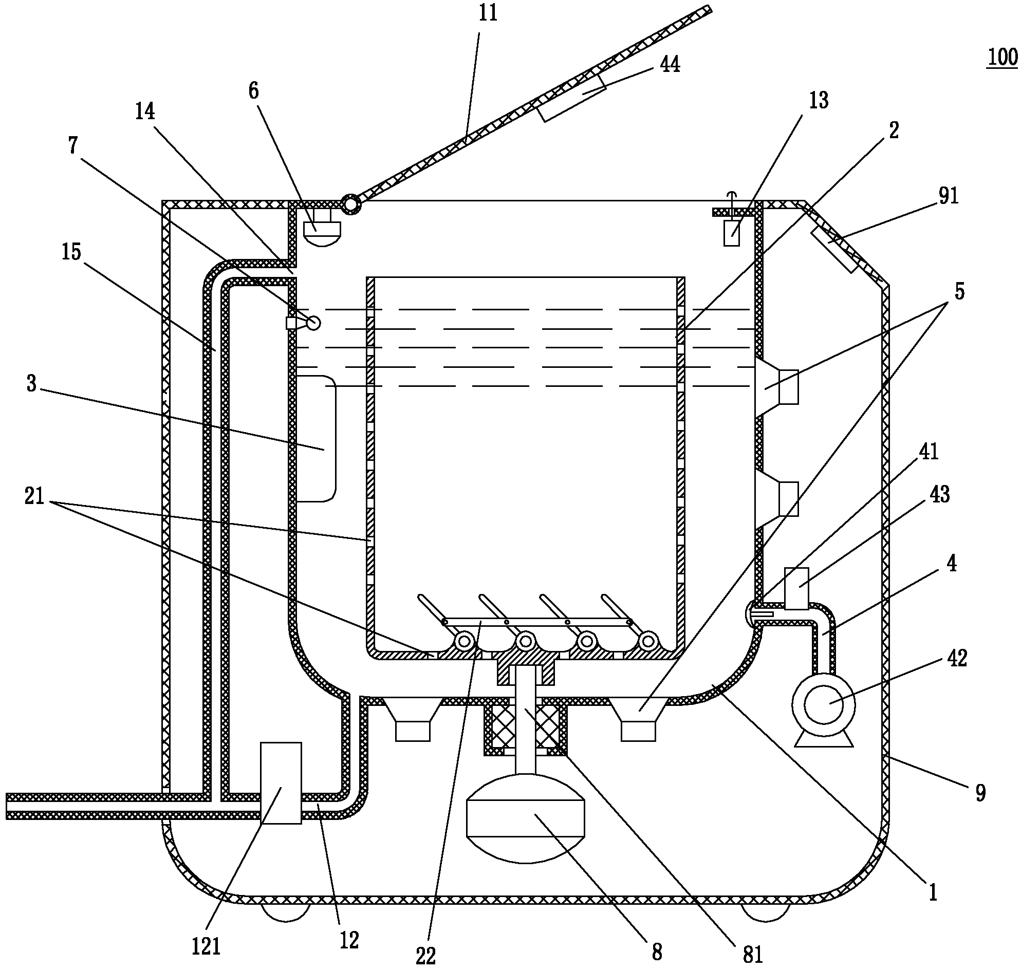
[0032] Such as figure 1 As shown, the present invention proposes a cleaning and disinfecting machine 100, the cleaning and disinfecting machine 100 includes a cleaning tank 1, the top of the cleaning tank 1 is provided with a top cover 11, and the bottom of the cleaning tank 1 is provided with a drainage pipeline 12, and the drainage pipeline 12 is provided with a drainage solenoid valve 121; a cleaning frame 2 is rotatably set in the cleaning tank, and the cleaning frame 2 can rotate along a rotating shaft arranged in any direction. In this embodiment, the cleaning frame 2 is along the A vertical shaft is set in the cleaning tank to rotate; the cleaning tank 1 is also provided with an electrolytic water generating device 3 .

...


PUM


Abstract

The present invention relates to a cleaning and disinfection apparatus. The cleaning and disinfection apparatus comprises a cleansing tank. The top of the cleaning tank is provided with a top cover, the bottom of the cleaning tank is provided with a drainage pipe. A cleaning rack is rotationally arranged in the cleaning tank. The cleaning tank is provided with an electrolysis and water generating device. According to the cleaning and disinfection apparatus, the electrolysis and water generating device is arranged in the cleaning tank, the electrolysis and water generating device and the cleaned material can maintain the short-distance contact, when the cleaning and disinfection apparatus works, the generating hydroxyl radical can directly enter the water containing the processed material, and contacts the processed material in a short time, such that the cleaning and disinfection efficiency can be improved; with the rotation effect of the multifunctional cleaning rack, the stirring water flows through the electrolysis and water generating device, such that the hydroxyl radical can provide a effect for the surface of the processed material and the internal of the water so as to achieve the highest efficiency of the cleaning and disinfection apparatus.

Description

technical field [0001] The invention relates to a disinfection and cleaning equipment, in particular to a cleaning and disinfection machine for various foods such as fruits and vegetables, articles for infants and young children, tableware and chopsticks. Background technique [0002] Nowadays, the problem of food pollution around people is becoming more and more serious. In addition to the original pesticide residues, reports of various food safety problems such as hormone residues and antibiotic abuse are common. In this context, a large number of food cleaning and disinfection machines have appeared on the market. . However, most of the existing cleaning and disinfecting machines use the ozone aeration method for disinfection. Not only the disinfection efficiency is low, but also the residual ozone in the water will cause harm to the human body. [0003] In recent years, as a brand-new disinfection and sterilization method, hydroxyl radical generator has been paid more a...

Claims


Application Information

Patent Timeline
Patent Type & Authority Applications(China)
IPC IPC(8): A61L2/14A61L2/18A61L2/10B08B3/04B08B3/12A23L1/015A47J43/24A47L15/10A47L15/44A61L101/10A23L5/20
Inventor 何鲁敏
Owner BEIJING YADU ENVIRONMENTAL PROTECTION TECH
Why Eureka
Try Eureka