Depth uniformity control method for laser surface quenching hardening layer and device thereof

A technology of laser surface quenching and hardened layer depth, which is applied in the direction of temperature control using electric methods, can solve problems such as unevenness, and achieve the effect of uniform hardened layer depth

Active Publication Date: 2012-02-22
上海岳乾激光科技有限公司
View PDF2 Cites 15 Cited by
  • Summary
  • Abstract
  • Description
  • Claims
  • Application Information

AI Technical Summary

Problems solved by technology

[0004] The present invention aims at the above-mentioned deficiencies existing in the prior art, and provides a laser surface quenching hardened layer depth uniformity control method and its device, so that the temperature along the thickness direction exceeds the phase transition point to reach the austenite state and rapidly cools to form martensite The depth of the hardened layer is equivalent to every point on the metal surface, and it is easy to control the depth of the hardened layer during laser surface quenching, and it also ensures that no fused layer or overheated layer appears on the metal surface, and greatly improves the temperature caused by the difference in cold and hot states. Inhomogeneity of Hardened Layer Depth in Scanning Direction

Method used


Image

  • Depth uniformity control method for laser surface quenching hardening layer and device thereof
  • Depth uniformity control method for laser surface quenching hardening layer and device thereof
  • Depth uniformity control method for laser surface quenching hardening layer and device thereof

Examples


Embodiment 1

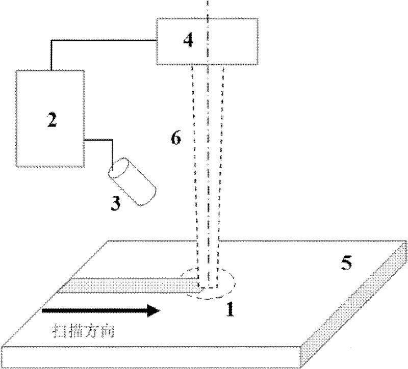
[0023] Such as figure 1 As shown, the control device involved in this embodiment includes: a control module 2 and an infrared enhanced CCD camera 3 and a laser 4 connected thereto respectively, wherein: the control module 2 obtains a molten pool image from the infrared enhanced CCD camera 3 and outputs power The control command is sent to the laser 4, and the output end of the laser 4 and the lens of the infrared enhanced CCD camera 3 face the area 1 to be treated on the substrate 5 respectively.

[0024] The infrared enhanced CCD camera 3 uses a special filter to filter visible light and laser light. After correction, the gray value of the captured image can reflect the temperature value of the corresponding point.

[0025] The control module 2 includes: a serial communication unit, an analog signal output unit, a human-machine interface unit, and a computer signal processing unit, wherein: the serial communication unit is connected with an infrared enhanced CCD camera and tr...

Embodiment 2

[0030] Such as figure 1 Shown, in the present embodiment, workpiece size is the die steel of 150mm * 60mm * 10mm (long * wide * thick); The heating peak temperature is set to be 1350 ℃ on the computer, and the focus size of the laser beam 6 that semiconductor laser outputs is 7.0mm * 1.5 mm, the focus of the laser beam 6 is located on the surface of the workpiece; when the laser beam 6 irradiates the surface of the workpiece at a scanning speed of 1.3m / min, a quenching zone is formed in the area scanned by the laser beam 6.

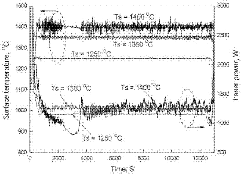
[0031] Such as figure 2 As shown, during the laser surface quenching process, the actual heating peak temperature of the workpiece surface detected by the infrared enhanced CCD camera is basically controlled at 1350°C; at the beginning, the workpiece is in a cold state, and a large laser power is required to ensure the actual heating peak of the workpiece surface When the temperature reaches 1350°C, as the workpiece is heated to a hot state, the laser p...

Embodiment 3

[0033] Such as figure 1 Shown, in the present embodiment, workpiece size is the die steel of 150mm * 60mm * 10mm (long * wide * thick); The heating peak temperature is set to be 1400 ℃ on the computer, and the focus size of the laser beam 6 that semiconductor laser outputs is 7.0mm * 1.5 mm, the focus of the laser beam 6 is located on the surface of the workpiece; when the laser beam 6 irradiates the surface of the workpiece at a scanning speed of 1.3m / min, a quenching zone is formed in the area scanned by the laser beam 6.

[0034] Such as figure 2 As shown, during the laser surface quenching process, the actual heating peak temperature of the workpiece surface detected by the infrared enhanced CCD camera fluctuated around 1400°C, and the laser power also fluctuated greatly; it was observed that there were traces of partial melting on the surface of the workpiece after quenching, indicating that the actual heating peak The temperature has reached above the melting point of ...


PUM


Abstract

A depth uniformity control method for a laser surface quenching hardening layer and a device thereof belongs to the technical field of material surface treatment. A charge coupled device (CCD) camera is enhanced by infrared to shoot temperature field images of a heating area in a quenching process, actual heating peak temperature can be obtained by analyzing the temperature field images, and laser power is fed back and controlled by closed loop control to adjust the actual peak temperature to heating peak temperature preset before quenching laser surface. When the preset heating peak temperature and the moving speed of laser is fixed values, uniformity of the depth of the hardening layer on the metal surface can be achieved. The depth uniformity control method enables temperature along the thickness direction to exceed phase transformation points to reach an austenite state and be quickly cooled to lead depth areas of a martensite layer to be matched at every point on the metal surface. Furthermore, the depth of the hardening layer is easy to control in laser surface quenching, a melting layer or an overheating layer is prevented from appearing on the metal surface, and the non-uniformity problem of the thickness of the hardening layer in the scanning direction caused by different cold and hot states is greatly resolved.

Description

technical field [0001] The invention relates to a method and a device in the technical field of material surface treatment, in particular to a method and a device for controlling the depth uniformity of a laser surface quenching hardened layer. Background technique [0002] Laser surface hardening is a surface heat treatment process that uses a laser beam to rapidly heat the surface of a steel material so that its temperature exceeds the phase transition point and reaches an austenite state. When the laser beam is removed, the surface of the material cools rapidly to form a martensitic hardened layer. During laser surface quenching, the laser beam has a small divergence angle and good directivity, and can accurately and locally quench the surface of the material through the light guide system; the laser heating speed is fast, and it is instantaneous local heating and quenching, the heat-affected zone is small, and the workpiece deformation is very small Small; rapid heating,...

Claims


Application Information

Patent Timeline
Patent Type & Authority Applications(China)
IPC IPC(8): C21D1/09G05D23/19
Inventor 李铸国黄坚张轲李瑞峰张悦
Owner 上海岳乾激光科技有限公司
Why Eureka
Try Eureka