Fluid driving structure high-speed rotating test device for verifying fluid-solid coupling algorithm
What is Al technical title?
Al technical title is built by PatSnap Al team. It summarizes the technical point description of the patent document.
A fluid-driven, fluid-structure coupling technology, applied in fluid dynamics tests, testing of machine/structural components, measuring devices, etc., can solve the problems of high production cost, long production cycle, high energy consumption and test cost, etc.
Active Publication Date: 2012-02-22
北京航数车辆数据研究所有限公司
View PDF5 Cites 5 Cited by
Summary
Abstract
Description
Claims
Application Information
AI Technical Summary
This helps you quickly interpret patents by identifying the three key elements:
Problems solved by technology
Method used
Benefits of technology
Problems solved by technology
As a general-purpose equipment for fluid mechanics test research, the water tunnel equipment has a large size and takes up a lot of space. The power system driving the water flow is very powerful, and the energy consumption and test cost are very high. If the test device is made according to 1:1, the production The cycle is long, the production cost is high, and the installation and testing of the measuring elements during the test are not convenient enough
Method used
Image
Click on the blue label to locate the original text in one second.
Reading with bidirectional positioning of images and text.
Examples
Embodiment Construction
[0048] Below in conjunction with accompanying drawing, the present invention is described in further detail: see accompanying drawing
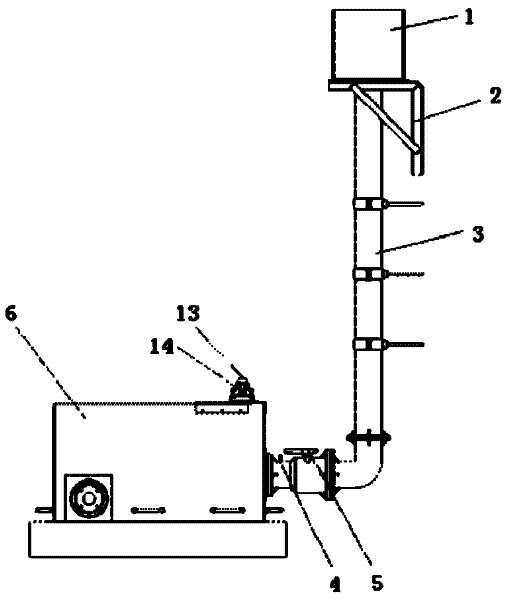
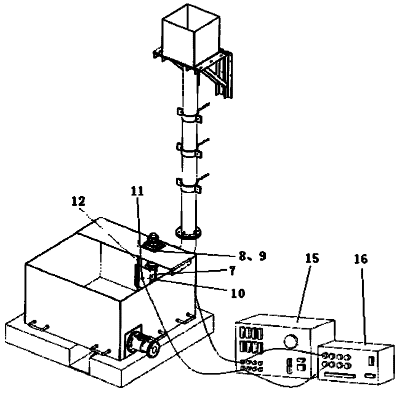
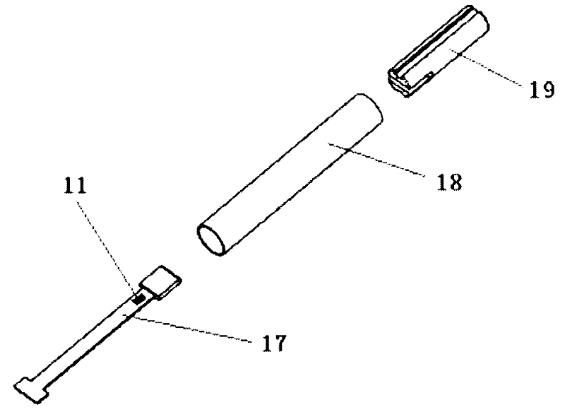
[0049] See Fig. 1, a fluid-driven structure high-speed rotation test device for verifying the fluid-solid coupling algorithm of the present invention, which includes a water tank 1, a water tank bracket 2, a PVC pipeline 3, a target flowmeter 4, a butterfly valve 5, a water tank 6, and a rotating shaft 7 , bearing 8, bearing seat 9, thin plate 10, strain gauge 11, gear lever 12, angular displacement sensor 13, tight elastic coupling 14, dynamic strain gauge 15 and intelligent signal acquisition and processing analyzer 16. The position connection relationship between them is:
[0050]The water tank 1 is placed on the water tank bracket 2 and placed at the highest point of the device. The bottom of the water tank 1 is connected to one end of the PVC pipeline 3, and the other end of the PVC pipeline 3 is connected to the water inlet on the side o...
PUM
Abstract
The invention relates to a fluid driving structure high-speed rotating test device for verifying the fluid-solid coupling algorithm, which comprises a water box, a water box support frame, a polyvinyl chloride (PVC) pipeline, a target type flow meter, a butterfly valve, a water tank, a rotating shaft, a bearing, a bearing seat, a thin plate, a strain sheet, a blocking rod, an angle displacement sensor, a clinging type elastic shaft coupler, a dynamic strain instrument and an intelligent signal collection processing analysis instrument, wherein the water box is placed on the water box support frame, one end of the PVC pipeline is communicated with the bottom of the water box, the other end of the PVC pipeline is connected with a water inlet at the side surface of the water tank, the PVC pipeline in a position near the water inlet of the water tank is provided with the butterfly valve, the target type flow meter is arranged at the upper end of the PVC pipeline arranged between the water inlet and the butterfly valve, the rotating shaft is vertically arranged in the water tank in a position near the water inlet, the thin plate is inserted into a through groove arranged in the middle of the rotating shaft, conducting wires led out from the strain sheet arranged on the thin plate and the target type flow meter are connected with the dynamic strain instrument and the intelligent signal collection processing analysis instrument for collecting strain change time data, and a conducting wire led out from the angle displacement sensor is connected with a data collection plate of the angle displacement sensor for collecting the rotating angle change time data of the rotating shaft.
Description
(1) Technical field [0001] The invention relates to a test device capable of realizing the rotation of an underwater structure driven by a high-speed fluid, in particular to a high-speed rotation test device of a fluid-driven structure for verifying a fluid-solid coupling algorithm, which is mainly used to verify various fluid-solid coupling simulations The accuracy and applicability of the algorithm can replace complex and expensive underwater tests, study the relationship between structural dynamic response and fluid driving parameters, explore the fluid-solid coupling mechanism and scale law through test data, and provide a theoretical basis for underwater structure design , which belongs to the field of ocean ship engineering and weapon industry engineering technology. (2) Background technology [0002] The plate is the basic unit of underwater structure design. The process of movement and deformation of thin plates impacted by high-speed water flow is a process of flui...
Claims
Application Information
Patent Timeline
Application Date:The date an application was filed.
Publication Date:The date a patent or application was officially published.
First Publication Date:The earliest publication date of a patent with the same application number.
Issue Date:Publication date of the patent grant document.
PCT Entry Date:The Entry date of PCT National Phase.
Estimated Expiry Date:The statutory expiry date of a patent right according to the Patent Law, and it is the longest term of protection that the patent right can achieve without the termination of the patent right due to other reasons(Term extension factor has been taken into account ).
Invalid Date:Actual expiry date is based on effective date or publication date of legal transaction data of invalid patent.