Refrigeration heating system semi-physical simulation experimental method

A semi-physical simulation and test method technology, applied in the field of improvement of refrigeration and heating system simulation test methods, can solve the problems of long production cycle of system accessories, huge system, large compensation, etc.

Active Publication Date: 2012-02-22
XIAN AIRCRAFT DESIGN INST OF AVIATION IND OF CHINA
View PDF5 Cites 14 Cited by
  • Summary
  • Abstract
  • Description
  • Claims
  • Application Information

AI Technical Summary

Problems solved by technology

However, this test method has the following disadvantages: first, the system is huge, there are many accessories, and the production cycle of the system accessories is long; second, it consumes a lot of compressed air, resulting in a large compensation; material resources

Method used


Image

  • Refrigeration heating system semi-physical simulation experimental method
  • Refrigeration heating system semi-physical simulation experimental method
  • Refrigeration heating system semi-physical simulation experimental method

Examples


Embodiment 1

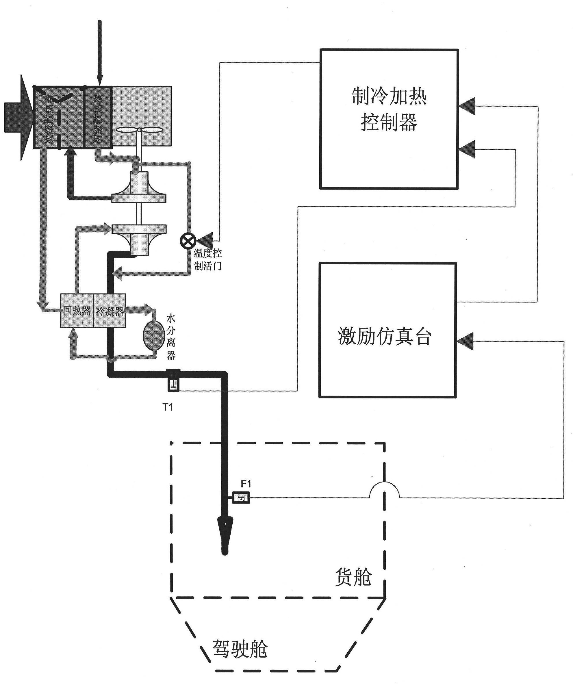
[0082] figure 1 Among them, the working principle of the refrigeration component is: the high-temperature and high-pressure gas drawn from the engine is cooled by the ram air in the primary heat exchanger, enters the compressor and is compressed to a higher pressure and temperature, and then enters the secondary heat exchanger for cooling. The supply air is cooled by cool air from the water separator as it passes through the regenerator. In the condenser, the moisture in the air is condensed from a vapor state to a liquid state under high pressure. After passing through the water separator, the air containing a small amount of condensed water droplets passes through the cold end of the regenerator to cool the air supply on the hot side and prevent the turbine from icing. The air supply is expanded and cooled by the turbine, and the shaft power generated during the expansion drives the compressor and the fan to rotate, and the heat energy is converted into mechanical energy, so...

Embodiment 2

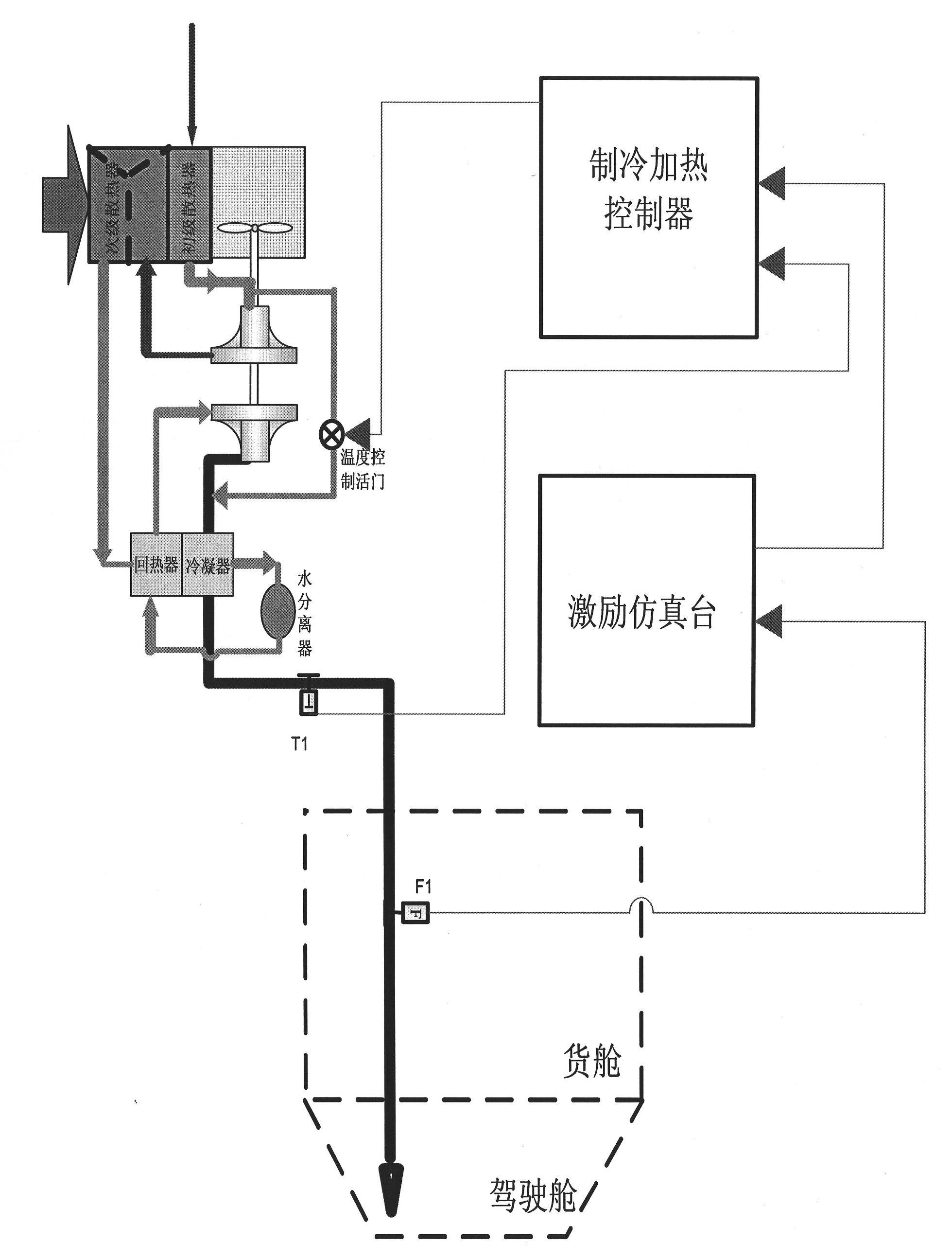
[0127] The cooling and heating assembly, excitation simulation platform, and cooling and heating controller in Embodiment 2 are the same as those in Embodiment 1.

[0128] experiment procedure:

[0129] First, as shown in the figure above, connect the above-mentioned cooling and heating controller, a set of real cooling components and the excitation simulation platform through wires;

[0130] The cooling and heating controller is connected with the temperature control valve in the real cooling component and the outlet temperature sensor of the cooling component through wires, and the cooling and heating controller controls the temperature control valve through the 28V / PWM output interface; at the same time, the cooling and heating controller and the excitation simulation platform are connected through wires Connection, the cooling and heating controller receives the simulation signal of the excitation simulation platform through the PT1000 resistance three-wire acquisition int...

Embodiment 3

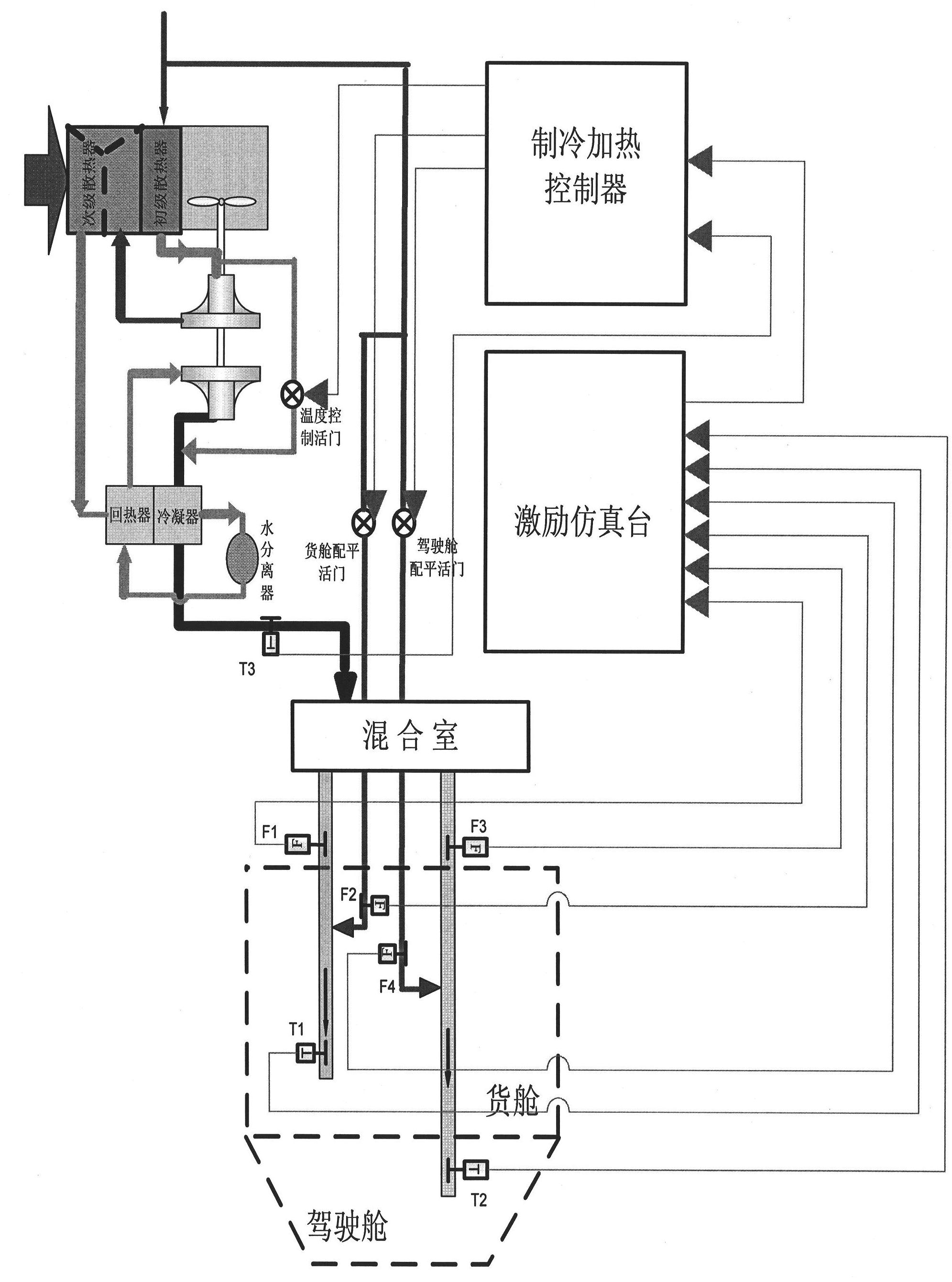
[0144] The cooling and heating assembly in Example 3 is based on the cooling and heating assembly in Example 1, adding a set of trim system, a mixing chamber, cockpit pipeline temperature sensor (T2), cockpit pipeline flow sensor (F3), cargo compartment Pipeline temperature sensor (T1), cargo tank pipeline flow sensor (F1). The trim system is composed of cockpit trim valve, cargo compartment trim valve, cockpit trim flow sensor (F3), cargo compartment trim flow sensor (F2) and some conduits.

[0145] The excitation simulation platform and cooling and heating controllers in Embodiment 2 are the same as those in Embodiment 1.

[0146] experiment procedure:

[0147] First, as shown in the figure above, connect the above-mentioned cooling and heating controller, a set of real cooling components and the excitation simulation platform through wires;

[0148] The cooling and heating controller is connected with the temperature control valve in the real cooling assembly, the outlet ...


PUM


Abstract

The invention provides a refrigeration heating system semi-physical simulation experimental method, belonging to the large-scale civil aircraft environment control field design technology. An experimental system comprises a refrigeration heating controller, a set of real refrigeration assembly and an excitation simulation bench. The method comprises the following steps: firstly, connecting the above parts together through a lead; secondly, setting up a refrigeration assembly physical simulation model in the excitation simulation bench, and transmitting a temperature value and a flow value of a real refrigeration assembly outlet to the refrigeration assembly physical simulation model; thirdly, setting up a cabin physical simulation model in the excitation simulation bench, and calculating a cabin temperature; fourthly, transmitting the cabin temperature to the refrigeration heating controller by the excitation simulation bench, and calculating a control rate of a temperature control valve by the refrigeration heating controller. The method in the invention has the following advantages: a defect in a system design can be discovered early, risk of an experiment is decreased, a processing period of system accessories is shortened, a quantity of the system accessories is reduced, a performance index and reliability of the whole system can be verified, and a systematic parameter and a control rule can be adjusted.

Description

technical field [0001] The invention belongs to the design technology in the field of large-scale civil aircraft environment control, and relates to the improvement of a simulation test method for a cooling and heating system. Background technique [0002] In the ground development process of refrigeration and heating systems, digital simulation methods are generally used in the conceptual design, preliminary design and detailed design stages. However, the refrigeration and heating system is a thermal inertial system, and it is difficult to establish accurate mathematical models for several subsystems or components in the system, which makes it difficult for pure digital simulation to truly reflect the characteristics of the system. [0003] Therefore, the traditional test method of large-scale aircraft cooling and heating systems brings all system accessories into the test and uses a real cockpit. However, this test method has the following disadvantages: first, the system...

Claims


Application Information

Patent Timeline
Patent Type & Authority Applications(China)
IPC IPC(8): G05B17/02
Inventor 党晓民王佳莉朱明洁
Owner XIAN AIRCRAFT DESIGN INST OF AVIATION IND OF CHINA
Why Eureka
Try Eureka