
Combined permanent-magnetic mechanism voltage/capacity adjusting switch

A technology of permanent magnet mechanism and capacity-adjusting switch, applied in the field of transformer components, can solve the problems of high cost, slow capacity-changing speed, easy to generate arcs, etc. Effect

Active Publication Date: 2012-02-22
北京博瑞莱智能科技集团有限公司
View PDF2 Cites 18 Cited by
  • Summary
  • Abstract
  • Description
  • Claims
  • Application Information

AI Technical Summary

Problems solved by technology

[0003] However, due to the slow rotation of the motor, the capacity change time generally takes several hundred milliseconds. Because of the slow capacity change speed, in order to avoid the voltage mutation caused by the asynchronous conversion of the high and low voltage coils, a transition resistor must be used between the main and auxiliary moving contacts. R connection, the resistor is easy to burn out
Also because of the slow speed of capacity change, arcs are easy to occur during capacity change, and long-term use will cause poor contact of contacts, increase of impurities in cooling oil, and decrease of insulation; in order to avoid this situation, corresponding protection devices are required, so that the volume of the transformer big, expensive
[0004] However, the distribution transformers on the 10kV distribution network not only need to adjust the capacity but also need to continuously adjust the output voltage. The current capacity adjustment switch obviously cannot meet this requirement.

Method used


Image

  • Combined permanent-magnetic mechanism voltage/capacity adjusting switch
  • Combined permanent-magnetic mechanism voltage/capacity adjusting switch
  • Combined permanent-magnetic mechanism voltage/capacity adjusting switch

Examples


Embodiment Construction

[0027] The combined permanent magnet mechanism voltage regulation and capacity regulation switch of the present invention will be further described below in conjunction with the accompanying drawings.

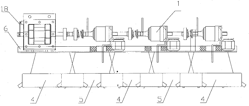
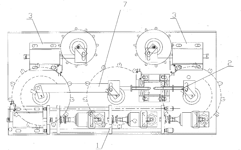
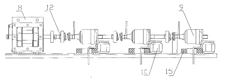
[0028] See attached Figure 1-2 As shown, a combined permanent magnet mechanism voltage regulating and capacity regulating switch according to the present invention includes a base plate 6, a pressure regulating disc switch 5 and a capacity regulating disc switch 4 connected to the base plate 6, the pressure regulating disc switch 5 and the volume-regulating disc switch 4 are located at the lower part of the base plate 6, and the upper part of the base plate 6 is provided with a voltage-regulating permanent magnet operating mechanism 3 and a capacity-regulating permanent magnet operating mechanism 2, and the pressure-regulating disc-shaped switch 5 and the described The voltage regulating permanent magnet operating mechanism 3 is connected, and the capacity regulating disc swit...


PUM


Abstract

The invention discloses a combined permanent-magnetic mechanism voltage / capacity adjusting switch which comprises two groups of permanent-magnetic mechanism voltage adjusting switches, one group of permanent-magnetic mechanism capacity adjusting switches, one group of bar-shaped direct-acting low-voltage permanent-magnetic vacuum load switches and a bottom plate, wherein the permanent-magnetic mechanism voltage adjusting switches and the permanent-magnetic mechanism capacity adjusting switches both comprise a permanent-magnetic operation mechanism and a disk-shaped switch; the permanent-magnetic operation mechanism is arranged above the bottom plate; the disk-shaped switch is arranged below the bottom plate; one end of the permanent-magnetic operation mechanism is connected with the disk-shaped switch, and the other end is connected with a travel control switch; and the bar-shaped direct-acting low-voltage permanent-magnetic vacuum load switch is fixed above the bottom plate. In the invention, as a voltage adjusting switch, a capacity adjusting switch and a low-voltage load control switch are combined, the volume is remarkably reduced, the occupied space is reduced, external linesare simplified, the cost of an automatic voltage / capacity adjusting distribution transformer is lowered, and the upgrading and transformation of a common distribution transformer are greatly facilitated.

Description

technical field [0001] The invention belongs to transformer components, and is a device for adjusting capacity and voltage of a transformer, in particular, it is suitable for capacity-regulating and voltage-regulating power distribution transformers with large load changes in rural power grids and large fluctuations in grid voltage. Background technique [0002] The currently widely used capacity regulating switch is generally composed of a housing, a switch core, and a gas protection device. The switch core is composed of a transmission member, a fast switching mechanism and a selector switch. The static contact is installed on the circumference of the switch core bar frame, and the moving contact is fixed on the main shaft support. When capacity adjustment is required, the motor drives the main shaft to rotate, and the moving contact contacts the corresponding static contact to realize the "Y-Δ" conversion of the transformer high-voltage winding and the "series-parallel" c...

Claims


Application Information

Patent Timeline
IPC IPC(8): H01F29/04H01H33/664H01H33/666H01F27/40
Inventor 魏贞祥杨福荣张中印马振邦
Owner 北京博瑞莱智能科技集团有限公司
Learn More