Geometric parameter measuring method for vertical shaft

A measurement method and a technology of geometric parameters, which are applied in the field of borehole diameter detection and well deviation limit value, can solve the problems that the ultrasonic ranging circuit cannot meet the measurement requirements, the measurement environment cannot have ferromagnetic substances, and the attenuation fluctuation of high-frequency ultrasonic waves is large. , to achieve simple and effective technical effects, highlighting technological progress, and suppressing echo interference

Inactive Publication Date: 2012-02-29
63653 FORCES PLA
View PDF4 Cites 12 Cited by
  • Summary
  • Abstract
  • Description
  • Claims
  • Application Information

AI Technical Summary

Problems solved by technology

[0002] At present, more advanced downhole directional measurement technologies include fluxgate and gyroscope, both of which have limitations; such as the requirement of the ferromagnetic environment of the fluxgate, that is, the measurement environment cannot have ferromagnetic substances; the gyroscope must be calibr

Method used


Image

  • Geometric parameter measuring method for vertical shaft
  • Geometric parameter measuring method for vertical shaft
  • Geometric parameter measuring method for vertical shaft

Examples


Embodiment approach

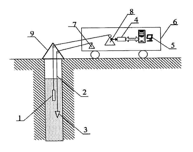
[0029] Implementation plan: the reference rope method is adopted, and the downhole instrument 1 and the reference rope 2 are arranged on the support 9 at the wellhead; the downhole instrument 1 is connected with the built-in cable winch 8 of the instrument car 6 and the computer 5 interface of the uphole instrument 4, and its measurement is recorded. Data; it is connected with the reference rope 2 of the heavy hammer 3 and the built-in reference rope winch 7 of the instrument car 6 to control its lifting; the measurement is implemented step by step;

[0030] ① Designed for a water-bearing vertical shaft with a depth of 900 meters and a diameter of 2.5 meters. The underground water pressure is high, the water quality is turbid, and the water temperature changes greatly;

[0031] ②The design adopts a separate structure, which is divided into an upper-hole tool 4 and a down-hole tool 1. The upper-hole tool 4 and the down-hole tool 1 are connected by an armored 4-core twisted-pair ...


PUM

PropertyMeasurementUnit
Depthaaaaaaaaaa
Diameteraaaaaaaaaa

Abstract

The invention discloses a geometric parameter measuring method for a vertical shaft. A reference rope method is adopted, namely an underground instrument and a reference rope are arranged on a bracket at a wellhead; the underground instrument is connected with a built-in cable winch in an instrument vehicle and a computer interface of a ground instrument and used for recording data; the reference rope tied with a heavy hammer is connected with a built-in reference rope winch in the instrument vehicle and used for adjusting lifting of the reference rope winch; and circuits are coordinated. The method comprises the following steps of: putting the underground instrument into the well at a distance of 50 centimeters from a logging instrument, lowering the reference rope vertically, obtaining the measurement result of the azimuth of the reference rope when the size of an obstacle is greater than 1/2 of the wavelength of sound wave and the sound wave is reflected, and further determining the actually measured relative azimuth; and measuring an auxiliary sound velocity, namely fixing a sound velocity by using the distance between the reference rope and the underground instrument, and calculating the distance of the actually measured azimuth. Deviation of signal initial time judgment is eliminated by introducing a logarithmic amplifying circuit in the measurement circuits, signal fluctuation caused by power frequency interference is eliminated by adopting a power frequency filter, the measurement precision of the shaft diameter reaches 1 millimeter, and the effective measurement distance in turbid water reaches 3.0 meters. The method is suitable for the water-containing vertical shaft with the depth of 0 to 1,000 meters and the diameter of 1 to 3 meters.

Description

technical field [0001] The invention relates to the ultrasonic ranging technology in the field of engineering technology, and is especially suitable for the detection of the limit value of the well deviation and the well diameter in the harsh environment, and the method provided is scientific and reasonable, fast and practical. Background technique [0002] At present, more advanced downhole directional measurement technologies include fluxgate and gyroscope, both of which have limitations; such as the requirement of the ferromagnetic environment of the fluxgate, that is, the measurement environment cannot have ferromagnetic substances; the gyroscope must be calibrated before measurement; Accurate distance measurement requires a higher frequency of the ultrasonic system; in addition, in the turbid water environment, the high-frequency ultrasonic attenuation is rapid and the fluctuation is large, and the general ultrasonic distance measurement circuit is difficult to meet the...

Claims


Application Information

Patent Timeline
IPC IPC(8): E21B47/02E21B47/08E21B47/14
Inventor 彭映成李艳洁赵建伟鲁辉钱海
Owner 63653 FORCES PLA
Why Eureka
Try Eureka