Differential phase-contrast imaging with circular gratings

A phase-contrast imaging and grating technology, which is used in materials analysis, applications, and instruments for radiological diagnosis using radiation to avoid edge distortion, simplify phase recovery, and reduce demand.

Inactive Publication Date: 2012-02-29
KONINKLIJKE PHILIPS ELECTRONICS NV
View PDF4 Cites 17 Cited by
  • Summary
  • Abstract
  • Description
  • Claims
  • Application Information

AI Technical Summary

Problems solved by technology

[0003] However, in order to provide an image of reasonably good quality, it may be necessary to perform moderate positioning accuracy and non-trivial phase correction at the time of migration

Method used


Image

  • Differential phase-contrast imaging with circular gratings
  • Differential phase-contrast imaging with circular gratings
  • Differential phase-contrast imaging with circular gratings

Examples


Embodiment Construction

[0038] The examples in the drawings are schematic and not to scale. In different figures, similar or identical elements are provided with the same reference numerals.

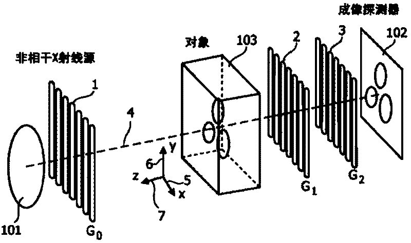
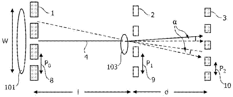
[0039] Figure 1A The measurement setup for differential phase-contrast imaging with linear gratings is shown. An incoherent X-ray source is used, represented by a focal spot 101 . The radiation beam emitted by the source has an optical axis 4 . First, the beam passes through the absorbing grating 1 (G 0 ). The beam then passes through the object of interest 103 and then through the phase grating 2 (G 1 ). Thereafter, the beam passes through a second absorption grating 3 (G 2 ), the second absorption grating 3 (G 2 ) is arranged before the imaging detector 102.

[0040] Reference numeral 5 depicts an x-axis, reference numeral 6 depicts a y-axis, and reference numeral 7 depicts a z-axis, which is arranged parallel to the optical axis 4 .

[0041] Figure 1B show Figure 1A A cross-sectional view of the...


PUM


Abstract

The invention relates to an X-ray differential phase-contrast imaging system which has three circular gratings. The circular gratings are aligned with the optical axis of the radiation beam and a phase stepping is performed along the optical axis with the focal spot, the phase grating and/or the absorber grating. The signal measured is the phase-gradient in radial direction away from the optical axis.

Description

technical field [0001] The present invention relates to phase contrast imaging. In particular, the invention relates to a phase contrast imaging device, a phase contrast imaging method, a computer readable medium and a program element for examining an object of interest. Background technique [0002] To examine an object of interest with electromagnetic radiation, visible or invisible light or X-rays can be used. The method disclosed in "Phase retrieval and differential phase-contrast imaging with low-brilliance X-ray sources" by Pfeiffer et al., Nature Physics 2006, in the field of X-ray differential phase-contrast imaging (DPC) is based on an extension of Talbot interferometry. This extension includes the addition of a third grating that allows the use of polychromatic X-ray spectroscopy. Gratings used in this technique are formed from a linear groove arrangement, as depicted in FIGS. 1 and 2 . Detection of intensity variations via phase stepping allows measurement of t...

Claims


Application Information

Patent Timeline
Patent Type & Authority Applications(China)
IPC IPC(8): A61B6/03G01N23/04G21K7/00
CPCG21K7/00A61B6/4291A61B6/484A61B6/502
Inventor E·勒斯尔T·克勒G·马滕斯
Owner KONINKLIJKE PHILIPS ELECTRONICS NV
Why Eureka
Try Eureka