
Hybrid adaptive antenna array

A hybrid antenna and array technology, applied in antennas, radio wave measurement systems, direction finders using radio waves, etc., can solve problems such as difficulty in online calibration, increasing complexity and cost, and labor-intensive calibration of large analog arrays.

Active Publication Date: 2012-02-29
COMMONWEALTH SCI & IND RES ORG
View PDF3 Cites 48 Cited by
  • Summary
  • Abstract
  • Description
  • Claims
  • Application Information

AI Technical Summary

Problems solved by technology

However, analog beamformers have specific disadvantages
First, calibration of large analog arrays is labor-intensive, and in-line calibration is particularly difficult
second, special equipment must be used to implement beam tracking, thus increasing complexity and cost
Third, since the phase-shifted IF or RF signals are combined before conversion to baseband, there is no access to the baseband signals of the individual analog branches, limiting the ability to form selective beam patterns
These problems are especially acute for large analog arrays, where component defects and aging can severely degrade antenna performance

Method used


Image

  • Hybrid adaptive antenna array
  • Hybrid adaptive antenna array
  • Hybrid adaptive antenna array

Examples


Embodiment Construction

[0034] If steps and / or features with the same reference numerals are referenced in any one or more drawings, said steps and / or features have the same function or operation for purposes described herein, unless an intention to the contrary appears .

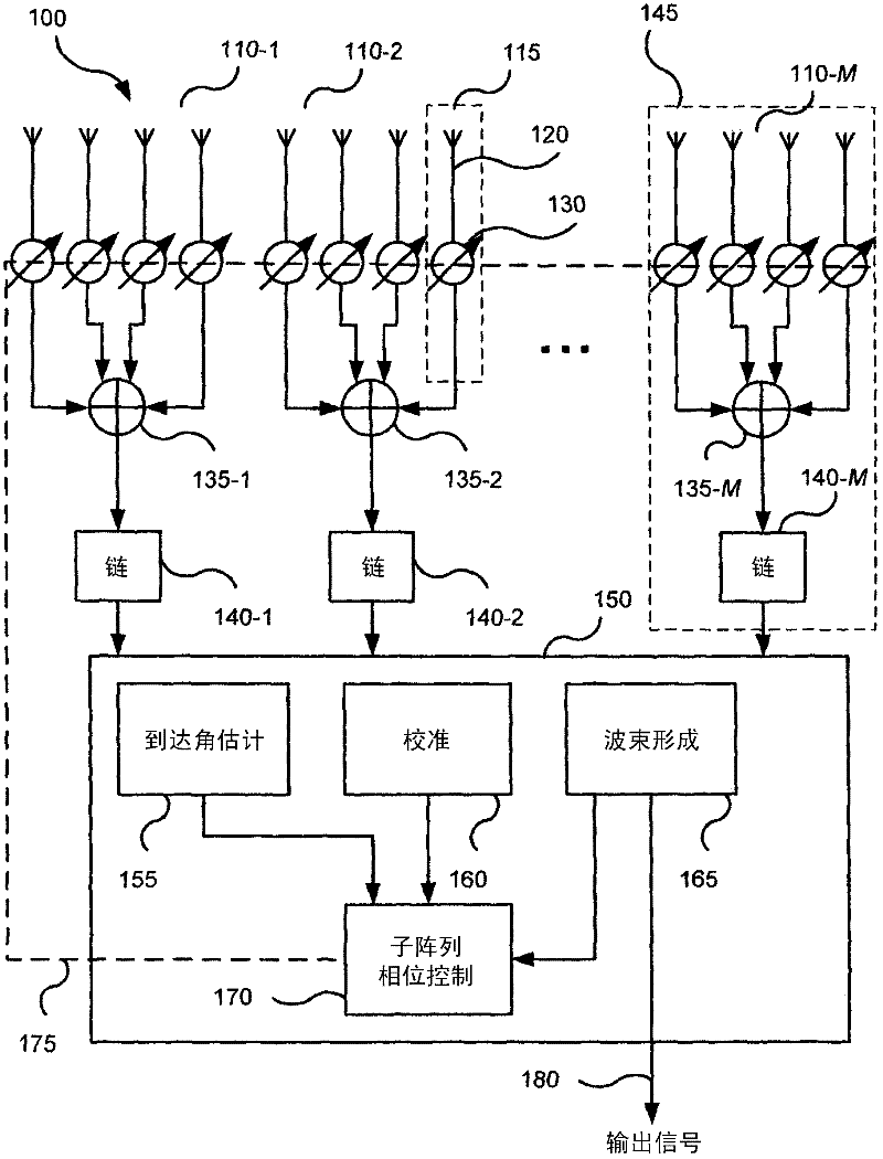
[0035] figure 1 A receive hybrid antenna array 100 is shown according to one embodiment. The antenna elements (eg, 120) in the array 100 are grouped into M analog beamforming sub-arrays 110-1, 110-2, . . . , 110-M.

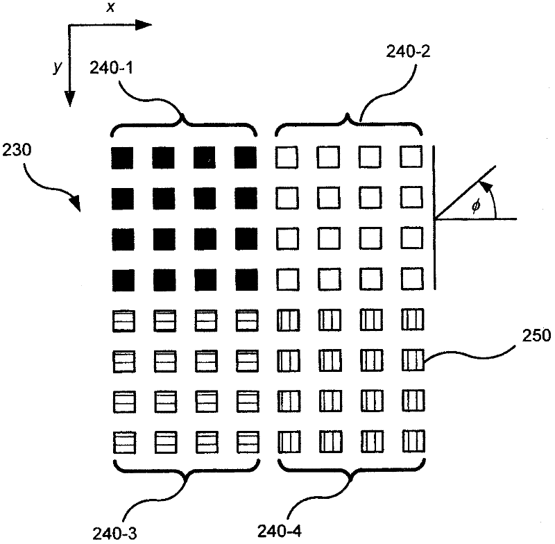
[0036] A hybrid array is said to have a planar configuration (planar array) if all subarrays lie in a single plane. A linear configuration (linear array) is a special case of a planar configuration in which all subarrays lie in a single line.

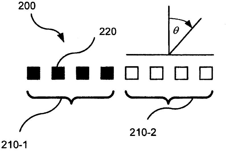
[0037] Figure 2a show figure 1 Example linear configuration 200 of hybrid antenna array 100 . The example linear array 200 includes two sub-arrays 210-1 and 210-2 arranged side-by-side, each sub-array 210-m including four evenly spaced cells, eg, 220, arranged along a li...


PUM


Abstract

Disclosed is a hybrid antenna array (100) comprising a plurality of digital branches (145), each digital branch including an analogue beamforming sub-array (e.g. 110-1), each sub- array having a plurality of antenna elements (120), a phase shifter (130) adapted to apply a phase shift to the signal from each antenna element, and a combiner (e.g. 135-1) adapted to combine the phase-shifted signals. Each digital branch also includes a signal chain (e.g.140-1) adapted to convert the output of the sub-array to baseband. The hybrid antenna array also comprises a digital processing module (150), including: an angle of arrival estimation sub-module (155) adapted to estimate an angle of arrival of a signal at the antenna elements; a phase control sub-module (170) adapted to control the phase shift applied by each phase shifter depending on the estimated angle of arrival; and a digital beamformer (165) adapted to combine the baseband signals from the digital branches using a weight vector to form an output signal (180).

Description

technical field [0001] The present invention relates generally to antenna design, and more particularly to architecture and methods for adaptive antenna arrays. Background technique [0002] Adaptive antennas are important subsystems for long-range, mobile and ad hoc wireless communication and sensing networks. The most powerful adaptive antenna architecture is a digital beamforming array, where each antenna element has an associated signal chain to convert the received signal from RF (radio frequency) to baseband, and the digital beamformer uses adaptive filtering techniques to baseband The signal is processed. Digital beamforming antenna arrays have the ability to simultaneously generate multiple antenna patterns, perform high-precision beamforming such as nulling, and generate output signals with maximum signal-to-noise-interference ratio (SNIR). Another advantage of the digital beamforming array architecture is that the online calibration of the different branches can ...

Claims


Application Information

Patent Timeline
IPC IPC(8): H01Q3/36G01S3/42H01Q3/26
CPCG01S3/023H01Q3/36
Inventor 英杰·杰伊·郭J·D·本顿V·佳久科小晶·黄
Owner COMMONWEALTH SCI & IND RES ORG
Learn More