Design method of stretch bending loading trace of novel stretch bender

A technology of loading trajectory and design method, which is applied in the design field of the tensile-bending loading trajectory of a new type of tension-bending machine, can solve the public report of the design method of the loading trajectory of the stretching-bending process that is not found, and affect the dimensional accuracy and strain of profile parts. Non-uniformity and other problems, to avoid uneven distribution of stretch, improve uniformity, and improve dimensional accuracy

Active Publication Date: 2012-03-07
SHANGHAI JIAO TONG UNIV
View PDF2 Cites 17 Cited by
  • Summary
  • Abstract
  • Description
  • Claims
  • Application Information

AI Technical Summary

Problems solved by technology

[0003] The loading trajectory of the traditional profile stretch bending process consists of three steps: pre-tensioning-bending-re-stretching. The existing profile stretch-bending technology focuses on the influence of pre-stretching and re-stretching on the dimensional accuracy of the part under the loading trajectory of the traditional process.
For profile stretch bending parts with large wrapping angle, due to the friction between the profile and the stretch bending die, if a supplementary drawing step is applied after the bending step, the supplementary tension can only affect the profile near the tension point Deformation can not affect the deformation of the profile on the other side away from the tension point, which will lead to uneven strain throughout the processed profile, thus affecting the dimensional accuracy of the processed profile parts
[0004] After searching the existing literature, no public report on the design method of the loading trajectory of the profile stretch bending process considering friction has been found so far

Method used


Image

  • Design method of stretch bending loading trace of novel stretch bender
  • Design method of stretch bending loading trace of novel stretch bender
  • Design method of stretch bending loading trace of novel stretch bender

Examples


Embodiment

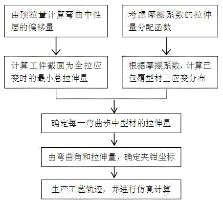
[0048] In this embodiment, an L-shaped aluminum alloy profile with a length of 2750mm is adopted, according to figure 1 Generate the loading trajectory of the profile stretch bending process, which specifically includes the following steps:

[0049] first step:

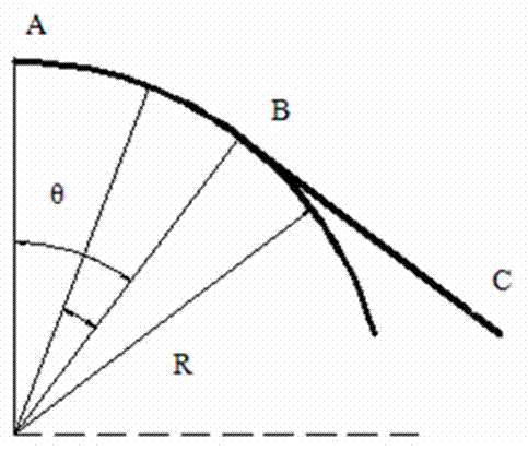
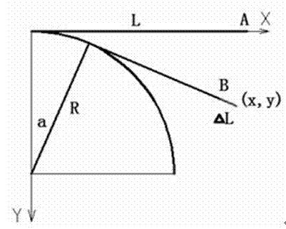
[0050] Regulation: is the pre-stretch amount, is the profile length, is the distance between the strain neutral layer and the lower surface when the profile is purely bent, is the bending radius of the profile, Offset to bring the neutral layer down for pre-pull, is the strain induced by the pretension, is the pure bending internal strain, is the distance from the lower surface of the profile to the strain-neutral layer after offset, is the angle of bend for each step, is the angle covered by the nth step, The bending angle is necessary to finish molding, is the length of the profile after the nth step of bending, is the total length of the contact part between the profile and the mold after ...


PUM

PropertyMeasurementUnit
lengthaaaaaaaaaa

Abstract

The invention provides a design method of the stretch bending loading trace of a novel stretch bender, comprising the following steps of: dispersing the bending trace curve of a profile into subtense substituted sections, dispersing the bending process in forming into bending steps, establishing a formula relationship among the elongation, profile length and bending radius of the profile in each bending step, and acquiring the elongations of the profile parts in each bending step; simulating the bending process, establishing the geometrical relationship between the coordinates of bending control points in each bending step to obtain the coordinates of the control points in each bending step; and introducing the coordinates of the control points in each bending step into simulation software to make calculation. According to the invention, a circular arc is dispersed and substituted with subtense, the profile is bent on the control points when moving along the subtense, and the stretching amount is applied in the bending process, thereby well averaging the internal strain of a large profile, reducing wrinkling and distortion and improving the dimensional accuracy; and because stretching is performed in the bending process, a supplementary stretching process can be saved, thus improving the production efficiency.

Description

technical field [0001] The present invention relates to a method in the field of profile stretch bending process design, in particular to a design method of a stretch bending process loading trajectory that can achieve uniform deformation, especially the design of the stretch bending loading trajectory of a new type stretch arm type stretch bending machine method. Background technique [0002] The profile stretch bending process is widely used in the manufacture of aircraft and automobile profile bending parts due to its high precision and good surface quality. The stretch bending process in aircraft manufacturing is mainly used to form skeleton parts such as fuselage, wing, air intake frame, and reinforcing edge strips; in automobile production, it is mainly used to form hollow aluminum profile bending parts for body structure and bumper. With the use of high-strength and light-weight profiles, such as high-strength aluminum alloys, magnesium alloys and titanium alloys, on...

Claims


Application Information

Patent Timeline
Patent Type & Authority Applications(China)
IPC IPC(8): B21D7/12
Inventor 于忠奇林忠钦刘传香陈仙风孔庆帅
Owner SHANGHAI JIAO TONG UNIV
Why Eureka
Try Eureka