Fully-automatic patch-type LED die bonder with new operation flows

A kind of operation process and chip-type technology, applied in the direction of electrical components, circuits, semiconductor devices, etc., can solve the problems that affect the automatic mass production of equipment, affect the production process and the quality of die bonding, and unfavorable the layout of the transmission mechanism, etc., to meet the needs of large Batch continuous work, improve operating rate and operability, easy to observe the effect of feeding and eliminating operational obstacles

Active Publication Date: 2014-04-30
GKG PRECISION MACHINE
View PDF5 Cites 0 Cited by
  • Summary
  • Abstract
  • Description
  • Claims
  • Application Information

AI Technical Summary

Problems solved by technology

This structure has the following defects: 1. Due to the setting of the left and right directions of the feeding channel, its inlet and outlet are located on the left and right side ends of the machine base, and usually the activity space at the left and right side ends of the machine base is relatively narrow, which brings a lot of inconvenience to the operation of feeding and discharging materials. It is not conducive to the layout of the transmission mechanism and affects the design concept of automated mass production of equipment
2. The dispensing module and the wafer are distributed on the same side of the feeding channel, and there are several die-bonding areas on the die-bonding bracket. The distance between different die-bonding areas and the dispensing module and the wafer is inconsistent. During arm dispensing and die bonding, it is very easy for work to interfere with each other, which affects the production process and the quality of die bonding, which in turn leads to a high defect rate in production and an increase in cost

Method used


Image

  • Fully-automatic patch-type LED die bonder with new operation flows
  • Fully-automatic patch-type LED die bonder with new operation flows
  • Fully-automatic patch-type LED die bonder with new operation flows

Examples


Embodiment 1

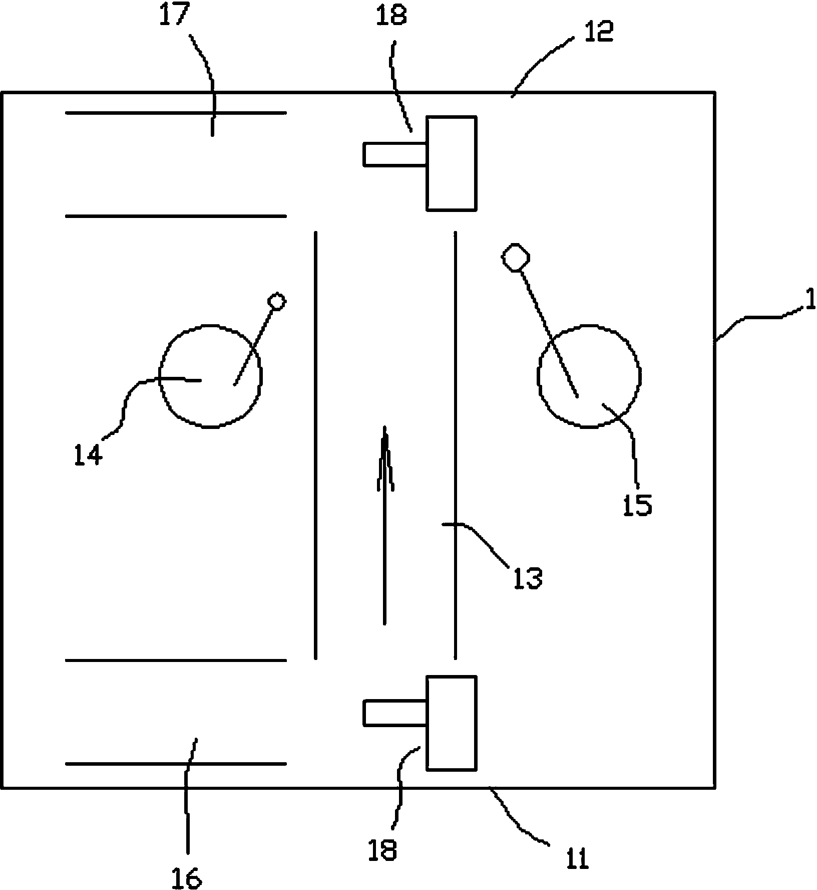
[0028] refer to figure 1 As shown, the fully automatic die-bonding machine of the SMD LED of the new operation process provided by the present invention is mainly used for processing the SMD LED, and it includes an organic base 1, which is provided with a feeding channel 13, a point Glue device 14 and chip pick-and-place device 15, etc., of course, also have a control unit and corresponding transmission mechanism (omitted in the figure) to meet the automatic die-bonding work. The frame 1 has a front end 11 facing the operator and a rear end 12 opposite to the front end 11; The area in between is transported and output from the rear end 12 of the machine base. The feeding channel 13 on the machine base 1 is arranged in a straight line toward the area between the glue dispensing device 14 and the chip pick-and-place device 15, so as to realize the feeding mode of forwarding and then out. In this embodiment, the feeding channel 13 is arranged in a straight line, and the glue d...

Embodiment 2

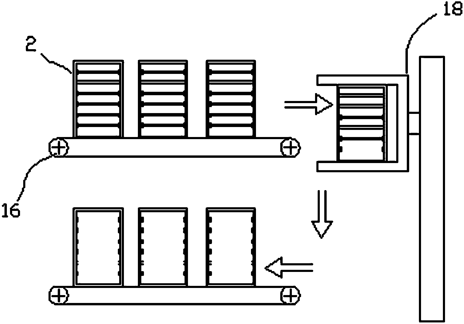
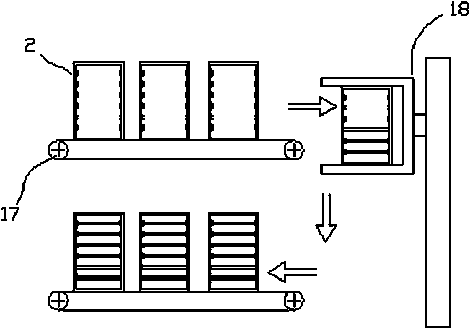
[0032] refer to Figure 4As shown, the fully automatic die-bonding machine of the SMD LED of the new operation process provided by the present invention is mainly used for processing the SMD LED, and it includes an organic base 1, which is provided with a feeding channel 13, a point Glue device 14 and chip pick-and-place device 15, etc., of course, also have a control unit and corresponding transmission mechanism (omitted in the figure) to meet the automatic die-bonding work. The base 1 has a front end 11 facing the operator and a rear end 12 opposite to the front end 11; the feed on the base 1 is taken and placed from the front end 11 and the rear end 12 of the base alternately towards the dispensing device 14 and chips Area delivery between devices 15. The feeding table of the front end 11 on the machine base and the feeding table of the rear end 12 are connected as a whole and move synchronously. The working mode is forward, front out and back in, back out, that is, two-w...


PUM


Abstract

The invention discloses a fully-automatic patch-type LED die bonder with new operation flows. The invention relates to the technical field of LED manufacturing equipment, in particular to a fully-automatic patch-type LED die bonder, which comprises a base, wherein the base is provided with a front end facing to an operator and a back end back to the front end; a dispensing device and a chip picking and placing device are arranged on the base; and feed materials on the base are conveyed to a region between the dispensing device and the chip picking and placing device from the front end and / or back end of the base in a unidirectional or bidirectional way. The fully-automatic patch-type LED die bonder breaks through the operation mode and the layout structure of the traditional die bonder; a working mode of front-in and back-out or front-in and front-out as well as back-in and back-out is adopted and a region at the back end of the base is fully utilized, so that the structure layout is easier, the structure combination is optimized, and feed materials and discharged materials flow more smoothly, therefore the production efficiency is improved, the operation rate and the operability of equipment are greatly improved, unnecessary interference during die bonding is reduced, and the production progress and the die bonding quality are ensured; and the operation of the front ends and the back ends of different die bonders can be mastered by one person, therefore human resources are saved and the production cost is reduced.

Description

technical field [0001] The invention relates to the technical field of LED manufacturing equipment, in particular to an LED crystal bonding machine. Background technique [0002] Die bonding machine is an important equipment for the production of light-emitting diodes (LED). Its working process is as follows: first, the feeding system transports the die-bonding support in the storage device to the feeding channel, and then the die-bonding support moves along the feeding channel and Stay at a certain position, at this time, the dispensing device on the base automatically dispenses the adhesive substance, that is, the adhesive substance is placed on the die-bonding area of ​​the die-bonding bracket, and then the chip is taken from the wafer by the automatic pick-and-place device, and The chip is bonded to the die-bonding area of ​​the die-bonding bracket to complete the die-bonding. Finally, the die-bonding bracket that has completed the die-bonding work continues to move alon...

Claims


Application Information

Patent Timeline
Patent Type & Authority Patents(China)
IPC IPC(8): H01L33/00
Inventor 邱国良
Owner GKG PRECISION MACHINE
Why Eureka
Try Eureka