Built-in secondary radiating antenna

A secondary radiation and secondary radiation technology, applied in the field of wireless communication, can solve problems affecting structural strength and appearance, and achieve the effect of saving antenna space and better performance

Inactive Publication Date: 2012-03-07
GUANGDONG OPPO MOBILE TELECOMM CORP LTD +1
View PDF7 Cites 114 Cited by
  • Summary
  • Abstract
  • Description
  • Claims
  • Application Information

AI Technical Summary

Problems solved by technology

This greatly affects the structural strength and appearance

Method used


Image

  • Built-in secondary radiating antenna
  • Built-in secondary radiating antenna
  • Built-in secondary radiating antenna

Examples


specific Embodiment

[0038] (1) specific embodiment basic structure

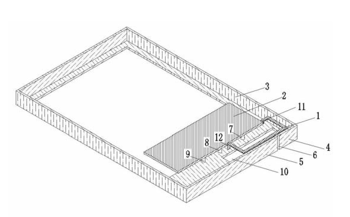
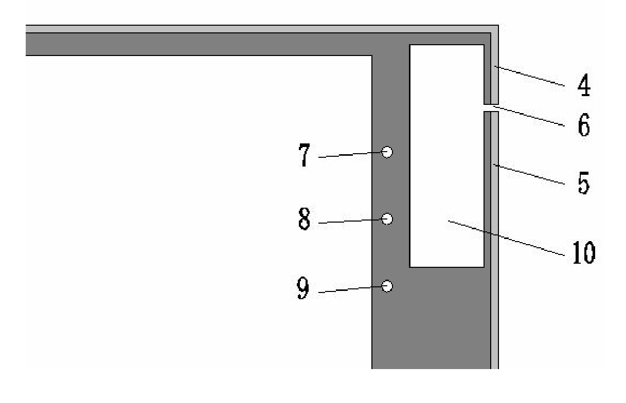
[0039] Such as figure 1 and 2As shown, the metal frame (metal shell) of the present invention requires specific modification, and this modification is the key technology of the present invention. The specific modification plan is that directly below the primary radiation unit 1, part or all of the metal of the metal shell needs to include a hollow 10; the size of the hollow 10 is changed accordingly according to the form, position, and working frequency band of the antenna. The edge part of the metal shell 3 is close to the position of the primary radiation unit 1, and a gap 6 is appropriately opened. The size and position of the gap 6 can be adjusted according to the needs. The gap 6 should be directly connected with the hollow 10. This feature is different from other existing antennas. main features of . The slit 6 cuts the edge of the metal casing to form an opening in the ring shape of the casing, thereby forming a second...

no. 1 example

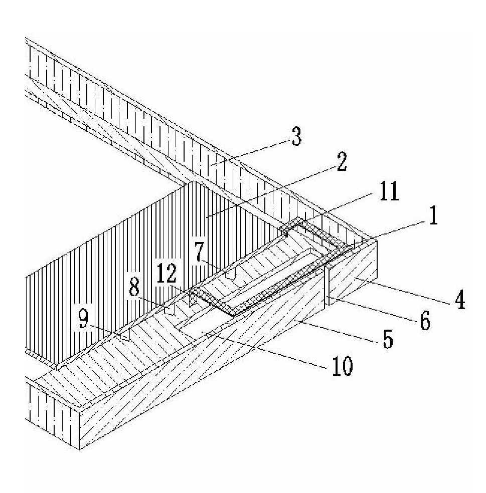
[0049] (2) The first embodiment: the primary radiation unit adopts a deformed loop antenna

[0050] Such as image 3 and 4 As shown, the first embodiment shows an antenna form implemented in the above-mentioned infrastructure environment, wherein the material of the primary radiation unit 1 can be all materials suitable for built-in antennas in the industry at present, including FPC, stainless steel sheet Stamping parts, copper sheet stamping parts, LDS process, etc. The above-mentioned primary radiation unit 1 can be installed on any suitable insulating material in the above-mentioned structure, and the installation bracket is omitted in the schematic diagram. The feeding method can adopt direct contact feeding methods such as thimbles installed on the circuit board 2, spring pins, welding, screw fixing, etc., or an antenna connector installed on the primary radiation unit 1 through a coaxial cable and the main board. The schematic diagram of the feeding mode is omitted in...

no. 2 example

[0054] (iii) The second embodiment: the primary radiation unit adopts IFA antenna

[0055] The second embodiment shows an antenna form of a primary radiation unit implemented in the above-mentioned infrastructure environment. The material of the primary radiation unit 1 can be all materials suitable for built-in antennas in the industry at present, including FPC and stainless steel sheet Metal stamping parts, copper sheet stamping parts, LDS process, etc. The above-mentioned primary radiation unit 1 can be installed on any suitable insulating material in the above-mentioned structure, and the installation bracket is omitted in the schematic diagram. The feeding method can adopt direct contact feeding methods such as thimbles installed on the main board circuit board 2, spring pins, welding, screw fixing, etc., or an antenna connector installed on the primary radiation unit 1 through a coaxial cable and The circuit boards 2 are connected, and the schematic diagram of the feedi...


PUM


Abstract

The invention relates to a built-in secondary radiating antenna. The antenna comprises: an antenna support; a primary radiating unit (1) on the support; a connection terminal of the primary radiating unit; and a secondary radiating unit; besides, the connection terminal of the primary radiating unit is electrically connected with a circuit board (2); and the secondary radiating unit, which is formed by a terminal metal casing (3), is coupled with the primary radiating unit and a resonance is jointly formed by the secondary radiating unit and the primary radiating unit on a working frequency; moreover, the terminal metal casing (3) consists of a hollowing (10) and / or a slit (6) and is electrically connected with a grounding terminal of the circuit board. According to the built-in secondary radiating antenna provided in the invention, a primary radiating unit and a secondary radiating unit form an integrated antenna; compared with a volume of a traditional built-in antenna, the volume of the built-in secondary radiating antenna is smaller; moreover, defects on a structure and an appearance of an all-metal frame antenna are avoided; and meanwhile, the antenna performance is excellent.

Description

technical field [0001] The invention relates to wireless communication, in particular to a built-in secondary radiation antenna, especially applicable to dual-mode or multi-mode mobile phones. Background technique [0002] With the development of wireless communication technology, especially in the current network society, wireless terminal equipment has become an indispensable tool for people's life and work. At the same time, the vigorous development of information technology makes the same wireless communication system equipped with more and more information subsystems. ; and the increase of the information subsystem will inevitably lead to the increase of antenna multi-band collection and antenna complexity. Looking at the wireless communication market, the thinness and miniaturization of handheld terminals are more favored by consumers in a highly competitive environment; and thin The trend of miniaturization will inevitably lead to smaller and smaller design space rese...

Claims


Application Information

Patent Timeline
Patent Type & Authority Applications(China)
IPC IPC(8): H01Q1/24H01Q1/36H01Q5/00H01Q19/00
CPCH01Q1/243H01Q5/378H01Q13/10
Inventor 曾元清
Owner GUANGDONG OPPO MOBILE TELECOMM CORP LTD
Why Eureka
Try Eureka