Cold plate performance test device

A testing device and cold plate technology, applied in the direction of measuring devices, instruments, etc., can solve the problems of difficulty in ensuring the heat flux density of electrical components, uneven thickness of thermally conductive silica gel, and insufficient thermal insulation measures to eliminate adverse effects, high pressure head, The effect of low heat loss

Inactive Publication Date: 2012-03-14
CHINA NORTH VEHICLE RES INST
View PDF5 Cites 18 Cited by
  • Summary
  • Abstract
  • Description
  • Claims
  • Application Information

AI Technical Summary

Problems solved by technology

[0004] Existing cold plate test devices are simple systems temporarily built on the test bench for a certain cold plate. The water pump is a single-stage centrifugal pump, resulting in a small measurement range. With the same heat flux density, the thermal insulation measures for the heat source on the surface of the cold plate to dissipate heat to the surrounding environment are not good enough. At the same time, due to the uneven thickness of the heat-conducting silica gel applied between the cold plate and the heating resistor module, the measurement error is large and the filter accuracy is low. Poor cleanliness in the system affects measurement accuracy

Method used


Image

  • Cold plate performance test device
  • Cold plate performance test device
  • Cold plate performance test device

Examples


Embodiment 1

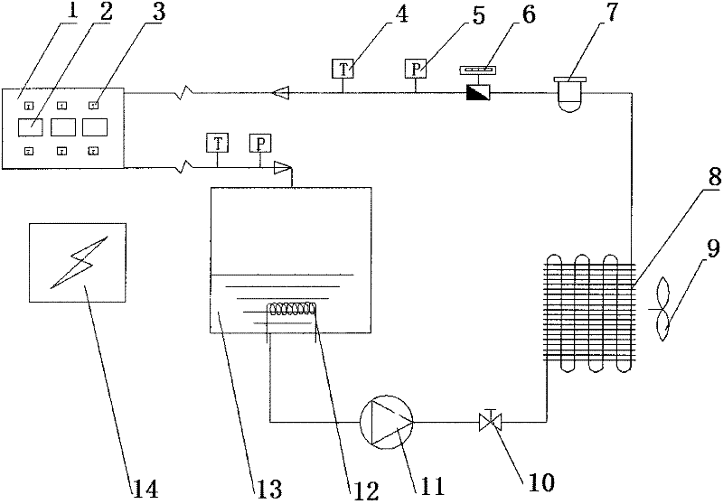
[0035] The cold plate performance testing device of the present embodiment includes a thermometer 4, a pressure gauge 5, a flow meter 6, a filter 7, a radiator 8, a flow valve 10, a water pump 11, a water tank 13 and a cold plate connected in series through pipelines. 1; the fan 9 is fixed together with the radiator 8 through the bracket; the electric heater 12 is installed on the side wall of the water tank 13 through screw connection; the heating resistance module 2 and the wall temperature sensor 3 are fixed on the surface of the cold plate 1 through bolts; the control unit 14 It is connected with the heating resistance module 2, the wall temperature sensor 3, the thermometer 4, the pressure gauge 5, the flow meter 6, the fan 9, the water pump 11, and the electric heater 12 through wires to form the control part of the device.

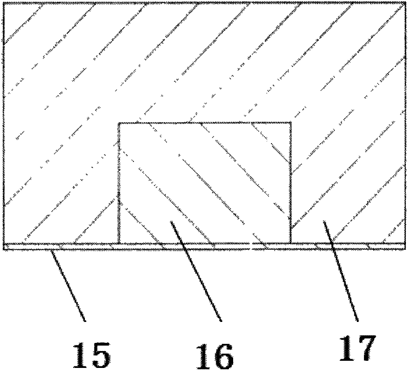
[0036] The heating resistance module 2 includes heat-conducting silicone grease, resistance and tetrapolyethylene fluoride insulation material.

[...

Embodiment 2

[0064] The performance testing device of the cold plate in this embodiment is basically the same as that in Example 1, except that the tetrafluoroethylene insulation material is covered around the resistor except the contact surface between the resistor and the cold plate, and its thickness is 20mm.

[0065] The thickness of thermal grease is 0.5mm.

Embodiment 3

[0067] The performance testing device of the cold plate in this embodiment is basically the same as that in Example 1, except that the tetrapolyethylene fluoride insulation material is covered around the resistor except the contact surface between the resistor and the cold plate, and its thickness is 15mm.

[0068] The thickness of thermal grease is 0.4mm.


PUM


Abstract

The invention provides a cold plate performance test device which is characterized by comprising a thermometer (4), a pressure meter (5), a flowmeter (6), a filter (7), a heat radiator (8), a flow valve (10), a water pump (11), a water tank (13) and a cold plate (1) which are sequentially connected together in series through a pipeline, wherein a fan (9) is fixed together with the heat radiator (8) through a bracket; an electric heater (12) is arranged on the side wall of the water tank (13) in a threaded connection manner; a heating resistance module (2) and a wall temperature sensor (3) are fixed on the surface of the cold plate (1) through bolts; and a control unit (14) is connected with the heating resistance module (2), the wall temperature sensor (3), the thermometer (4), the pressure meter (5), the flowmeter (6), the fan (9), the water pump (11) and the electric heater (12) through a conductive wire, so that a control part of the device is formed. The cold plate performance test device disclosed by the invention has the advantages of wide measurement range, small measurement error and high measurement precision.

Description

technical field [0001] The present invention relates to devices in the field of mechatronic engineering, in particular to testing devices. Background technique [0002] With the rapid development of electronic technology and the miniaturization of electronic equipment and electronic components, the volume power density of equipment is increasing, resulting in the continuous increase of heat dissipation power of equipment, especially in vehicle electronic equipment. If the heat dissipation of the electronic device cannot be dissipated in time, it will have a great impact on the performance of the electronic device, and even cause destructive damage, making the entire device invalid. Among the common failures of electronic equipment, as high as 50% to 60% of the equipment cannot work normally due to the high temperature of the electronic equipment. Therefore, it is particularly important to develop an efficient and reliable heat dissipation element, that is, an electronic col...

Claims


Application Information

Patent Timeline
Patent Type & Authority Applications(China)
IPC IPC(8): G01D21/02
Inventor 张佳卉周丽李欣刘建峰李云龙赵春伟石军赵自勤
Owner CHINA NORTH VEHICLE RES INST
Why Eureka
Try Eureka