
Mouth gag set for oral laryngeal surgery

A technology of mouth gag and oral cavity, which is applied in the direction of surgery, oral mirror, application, etc. It can solve the problems of long operation time, inconvenience, and failure to achieve lighting effects, etc., and achieve reasonable structural design, diverse functions, and ensure lighting and imaging effects Effect

Active Publication Date: 2012-03-21
申屠建林
View PDF4 Cites 7 Cited by
  • Summary
  • Abstract
  • Description
  • Claims
  • Application Information

AI Technical Summary

Problems solved by technology

Mainly reflected in: 1. The function of the surgical instrument is single, requiring multiple surgical instruments to cooperate with the operation, which is inconvenient and affects the efficiency of the operation; 2. In the treatment of diseases at the base of the tongue, the design of the spatula is not standardized, and the tongue is squeezed by the spatula , the tongue is easy to slide down or gushes out along both sides of the tongue depressor, which affects the surgical sight and lighting effect, reduces the surgical channel, and can only be completed with the help of some other auxiliary equipment, which makes the operation time too long and the operation difficulty increases; 3. In the treatment of laryngeal diseases, the design of the light source adjustment device is not standardized. The light source is installed on the adjustment device. The traditional external light source is used, which cannot achieve the ideal lighting effect and affects the surgical sight
[0003] Chinese patent, application number 200720030310.3, proposes a gag for opening the mouth. Its defect is that it has a single function and can only be used for opening the mouth. Inconvenient, affecting the effect of surgery

Method used


Image

  • Mouth gag set for oral laryngeal surgery
  • Mouth gag set for oral laryngeal surgery
  • Mouth gag set for oral laryngeal surgery

Examples


Embodiment 1

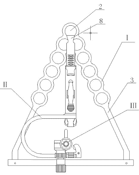
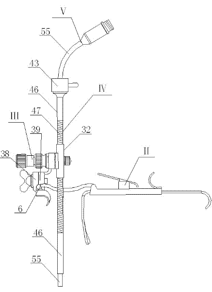
[0037] see Figure 1 ~ Figure 2 , this embodiment includes a support frame I, an opening device II, a light source adjustment device III, a light source channel IV and a throat light guide V, wherein the opening device II is connected to the support frame I, the light source adjustment device III is connected to the opening device II, and the light source Channel IV is installed on light source adjustment device III, and throat light guide V is installed on light source channel IV.

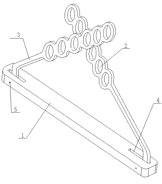
[0038] see image 3 , the support frame I includes a base plate 1 and two adjustment rods 3, the two ends of the base plate 1 are provided with connection grooves 4, the ends of the two adjustment rods 3 are snapped into the connection grooves 4, and are installed on the base plate 1 through connection pins 5 Above, the two adjusting rods 3 can rotate; the front ends of the two adjusting rods 3 are provided with a number of adjusting holes 2, the front ends of the two adjusting rods 3 cross each ...

Embodiment 2

[0055] see figure 1 and Figure 16 , this embodiment includes a support frame I, an opening device II, a light source adjustment device III, a light source channel IV and a laryngoscope VIII, wherein the opening device II is connected with the support frame I, the light source adjustment device III is connected with the opening device II, and the light source channel IV is installed On the light source adjustment device III, the laryngoscope VIII is installed on the light source channel IV.

[0056] see Figure 16 ~ Figure 17 The laryngoscope VIII includes a laryngoscope channel 75 and a laryngoscope seat 76, and the laryngoscope seat 76 is fixed to the laryngoscope channel 75; the laryngoscope channel 75 passes through the lock head 43 and the channel pipe 46 of the light source channel IV, The laryngoscope seat 76 snaps into the lock head 43 .

[0057] When in use, under the action of the light source adjustment device III, it can perform multi-directional and multi-angle...

Embodiment 3

[0061] see Figure 18 ~ Figure 19 , this embodiment includes a support frame I, an opening device II and an oral light guide IX, wherein the opening device II is connected to the support frame I, and the oral light guide IX is connected to the opening device II.

[0062] The oral light guide IX is connected to the bracket 6 of the opening device II; the oral light guide IX includes an oral light guide tube 64, an oral light guide interface 63, an oral light guide seat 56 and a light guide handle 59, the oral light guide The interface 63 is fixed to the oral light guide tube 64, the oral light guide seat 56 is welded and fixed to the oral light guide tube 64, and the oral light guide tube 64 is provided with a light guide fiber 54; the oral light guide seat 56 is provided with a caliper 61 to guide the light One end of the device handle 59 snaps into the caliper 61; the light guide handle 59 is connected with the oral light guide seat 56 through the light guide pin 60, the ligh...


PUM


Abstract

The invention relates to a mouth gag set for oral laryngeal surgery, which comprises a supporting rack, a mouth gag, a light source adjusting device, a light source channel, a laryngeal light guider, a laryngoscope, an aspirator and self-locking type tonsil gripping tongs. The mouth gag set is reasonable in structural design, integrates light, electricity, imaging and machinery, is multifunctional by means of different combinations, and can be effectively used for minimally invasive surgery of the laryngeal and the oral cavity of a patient. Surgery parts of the oral cavity and the laryngeal of the patient can be sufficiently exposed by the aid of the technical design of the mouth gag set, the surgery spaces of the oral cavity and the laryngeal of the patient can be adjusted, and further, the depth and the angle of the laryngeal of the patient can be adjusted flexibly. The mouth gag set can be used for imaging and illuminating a focus of the patient in a multidirectional and multi-angle manner, sufficient illumination and imaging effect of the surgery parts can be ensured, and a system further can be used for remote teaching and surgical recording.

Description

technical field [0001] The invention relates to a set of gags used for oral and throat surgery, which is a surgical treatment instrument for human throat, oral cavity and snoring diseases, and belongs to the field of medical equipment and surgery. Background technique [0002] In the treatment of human larynx, base of tongue, anterior symphysis, upper esophagus (diverticulum), tonsillectomy, palatopharyngoplasty, snoring and other operations in the medical field, due to the specificity of the physiological position of the human larynx, the surgical instruments currently used are Structural design defects have great limitations in the clinical operation process. Mainly reflected in: 1. The function of the surgical instrument is single, requiring multiple surgical instruments to cooperate with the operation, which is inconvenient and affects the efficiency of the operation; 2. In the treatment of diseases at the base of the tongue, the design of the spatula is not standardized...

Claims


Application Information

Patent Timeline
IPC IPC(8): A61B17/02A61B1/24A61B17/24A61M29/00F21V14/00F21V8/00F21W131/205
Inventor 申屠建林王荣光
Owner 申屠建林
Learn More