Eureka AIR delivers breakthrough ideas for toughest innovation challenges, trusted by R&D personnel around the world.

High-voltage circuit for electric locomotive unit

A high-voltage circuit and electric locomotive technology, applied in electric locomotives, locomotives, motor vehicles, etc., can solve the problems of poor synchronization, power loss of the whole vehicle, poor operation convenience, etc., and achieve convenient control, small power loss, and circuit structure. simple effect

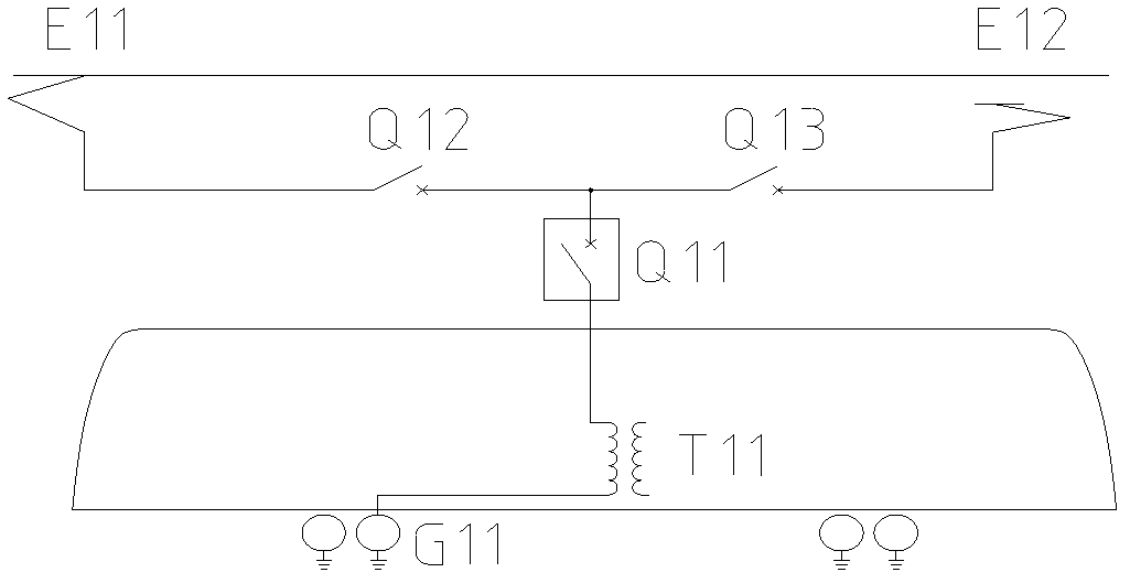
Inactive Publication Date: 2012-03-21
ZHUZHOU ELECTRIC LOCOMOTIVE CO LTD
View PDF6 Cites 28 Cited by
  • Summary
  • Abstract
  • Description
  • Claims
  • Application Information

AI Technical Summary

Problems solved by technology

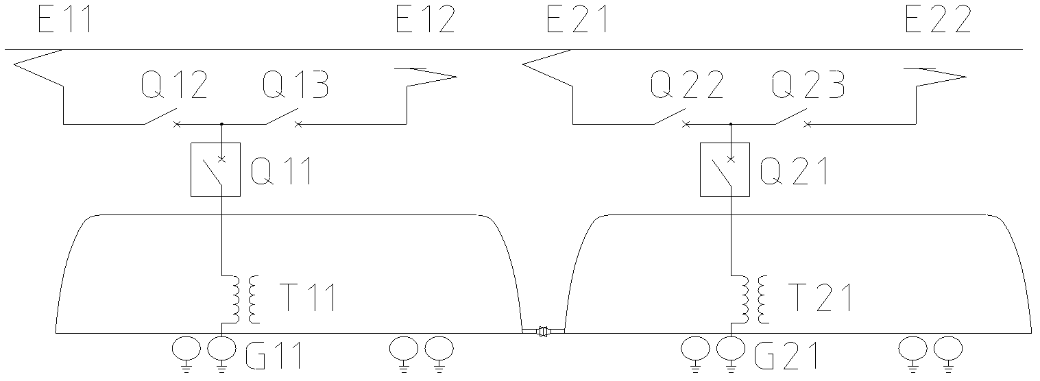
[0005] Restricted by factors such as the current on-off capacity of a single main circuit breaker, transformer capacity, converter equipment power, and traction motor power, the high-voltage main circuit for single-machine traction cannot meet the needs of high-power traction; figure 2 ) although the traction power can be increased, but the control is relatively independent, the synchronization between the locomotives is poor, and each locomotive needs to be equipped with drivers and passengers, which is not easy to use; figure 1 The high voltage circuit shown will have a total loss of vehicle power when the main circuit breaker fails, so the failure state availability of this high voltage circuit is not high

Method used


Image

  • High-voltage circuit for electric locomotive unit
  • High-voltage circuit for electric locomotive unit
  • High-voltage circuit for electric locomotive unit

Examples


Embodiment Construction

[0016] like image 3 As shown, an embodiment of the present invention includes two sets of high-voltage circuits with pantographs, and each set of high-voltage circuits with pantographs includes pantographs E11 / E31, high-voltage isolation switches Q12 / Q32, and main circuit breakers Q11 / Q31 , transformer T11 / T31, shaft end grounding device G11 / G31, in the first group of high-voltage circuits with pantographs, pantograph E11, main circuit breaker Q11, and high-voltage isolating switch Q12 are connected in sequence, and transformer T11 is connected in parallel to the main circuit breaker Between transformer Q11 and high-voltage isolating switch Q12, the low-voltage end of the primary winding of transformer T11 is grounded through shaft-end grounding device G11; in the second group of high-voltage circuits with pantographs, pantograph E31, main circuit breaker Q31, and high-voltage isolating switch Q32 is connected in sequence, the transformer T31 is connected in parallel between ...


PUM


Abstract

The invention discloses a high-voltage circuit for an electric locomotive unit. The high-voltage circuit for an electric locomotive unit comprises two groups of high-voltage circuits with pantographs, wherein each group of high-voltage circuit with the pantograph respectively comprises the pantograph, a high-voltage isolating switch, a main circuit breaker, a transformer and a shaft end grounding device; the pantograph, the main circuit breaker and the high-voltage isolating switch are connected with one another sequentially; a primary winding of the transformer is connected between the main circuit breaker and the high-voltage isolating switch in parallel; and the primary winding of the transformer is grounded through the shaft end grounding device. The high-voltage circuit for an electric locomotive unit also comprises a group of high-voltage circuit without the pantograph, wherein the group of high-voltage circuit without the pantograph comprises a high-voltage isolating switch, a transformer and a shaft end grounding device; and the three groups of high-voltage circuits are connected with a high-voltage tie cable through a locomotive roof high-voltage bus. The high-voltage circuit for an electric locomotive unit can meet the requirement of high-power heavy load traction, can realize isolation when high-voltage electric appliance parts break down, guarantees the minimum power loss of the whole locomotive after the failure is isolated, and has high availability in the whole locomotive failure state.

Description

technical field [0001] The invention relates to a high-voltage circuit for rail electric locomotives, in particular to a high-voltage circuit for electric locomotives. Background technique [0002] The electric locomotive obtains electric energy from the power supply network through the pantograph, and supplies power to the locomotive traction system and control system after passing through the main circuit breaker, high-voltage isolating switch, and transformer. [0003] The common operating modes of electric locomotives are single traction and double traction. The structure of the high-voltage main circuit for traction of a single electric locomotive is as follows: figure 1 As shown, during normal operation, the high-voltage side current passes through pantograph E11 / E12, high-voltage isolating switch Q12 / Q13, main circuit breaker Q11, and primary winding of transformer T11, and returns to the traction substation after being grounded by the shaft end grounding device G11....

Claims


Application Information

Patent Timeline
Patent Type & Authority Applications(China)
IPC IPC(8): B60L5/18B61C3/00
Inventor 颜罡金希红成本权张振华韩行一温中建康明明
Owner ZHUZHOU ELECTRIC LOCOMOTIVE CO LTD
Why Eureka
Eureka Blog
Learn More