
Axial flow impeller

An axial flow impeller and impeller technology, applied in the field of impeller components, can solve the problems of inability to produce finer droplets, inability to achieve higher speed, inability to generate spray airflow, etc., to avoid fluid impact damage, low maintenance costs, and use costs low effect

Inactive Publication Date: 2012-03-21
陈久斌
View PDF0 Cites 2 Cited by
  • Summary
  • Abstract
  • Description
  • Claims
  • Application Information

AI Technical Summary

Problems solved by technology

[0002] Existing impellers generally have defects such as high energy consumption, high noise, low pressure, low suction, inability to achieve higher speed, and inability to generate higher thrust.
[0003] Existing spray equipment has defects such as inability to produce finer droplets and higher pressure spray airflow
[0004] Existing propulsion equipment includes propellers, jet engines, etc., which have many defects such as low propulsion speed, high energy consumption and low efficiency

Method used


Image

  • Axial flow impeller
  • Axial flow impeller
  • Axial flow impeller

Examples


Embodiment Construction

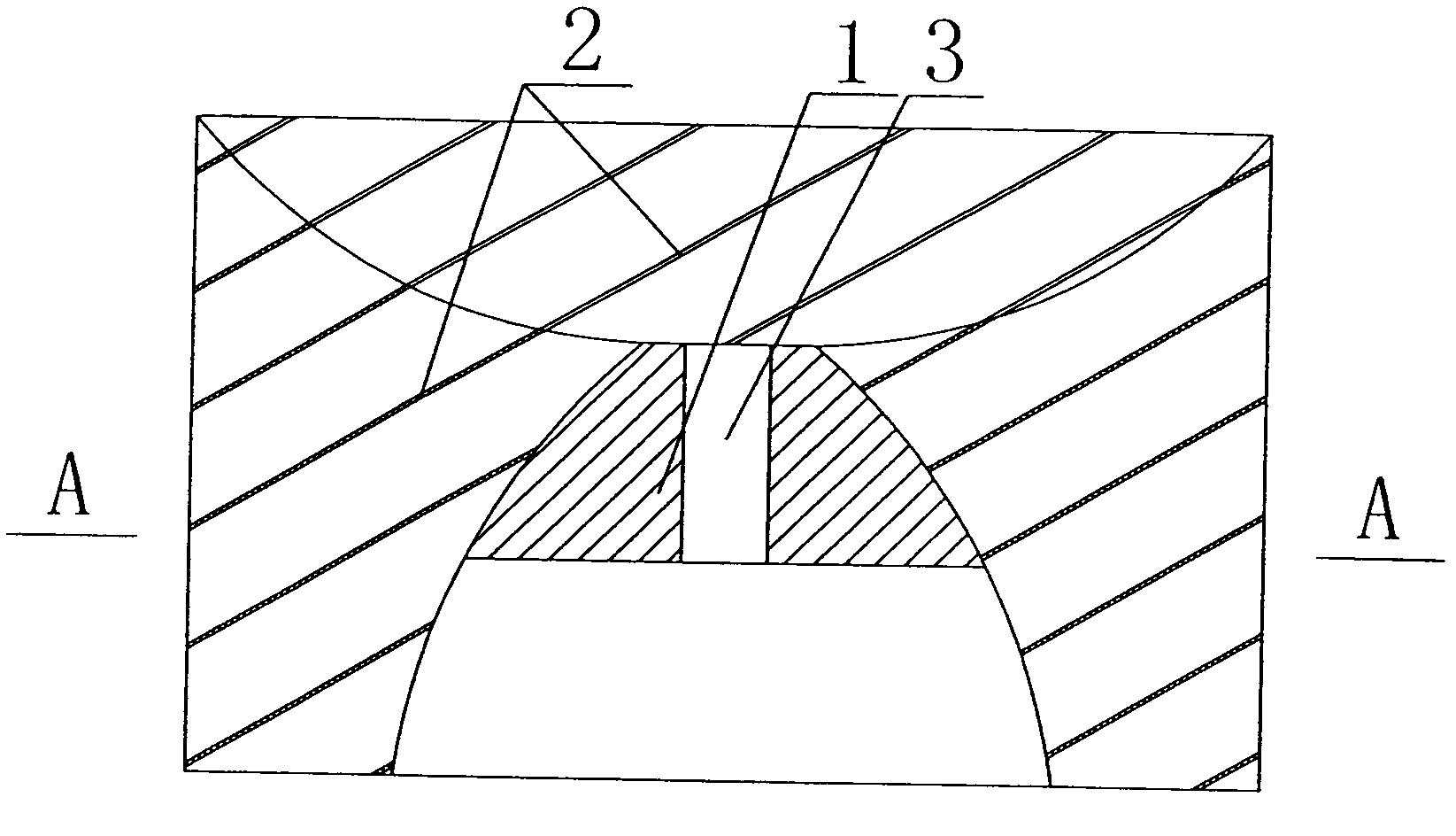
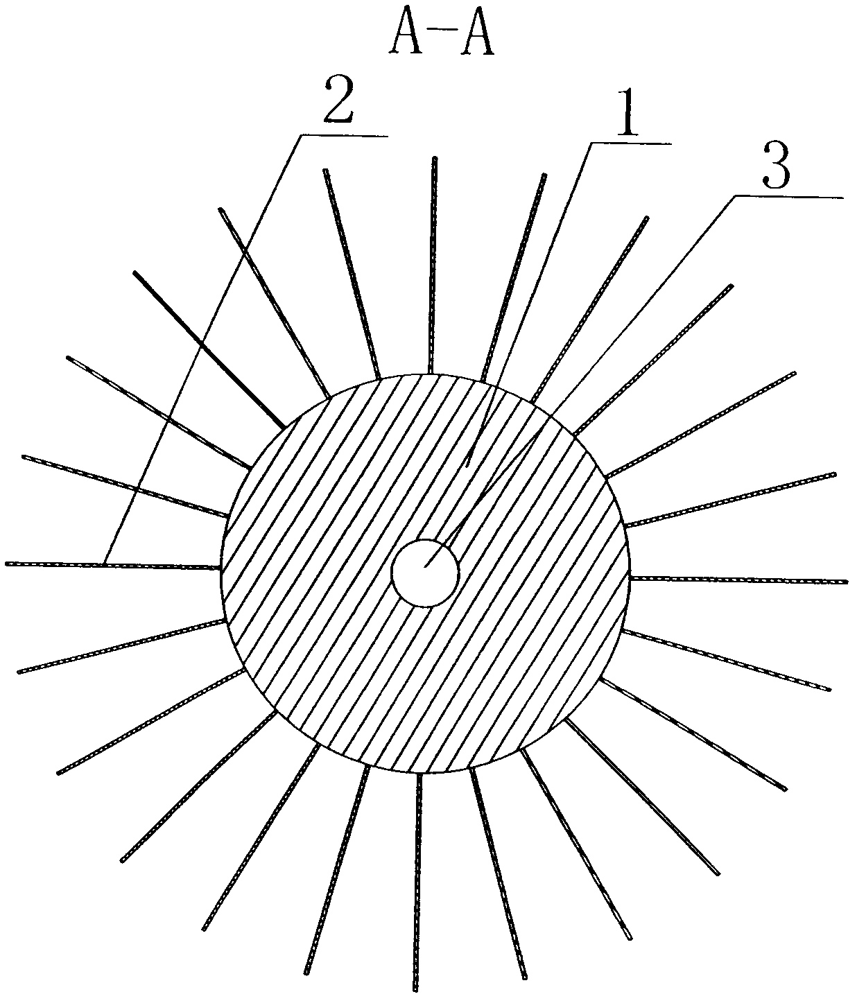
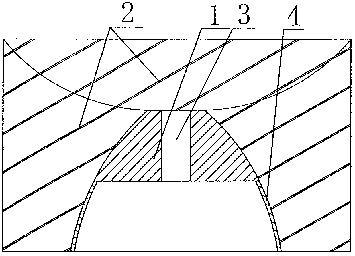
[0026] The main structure of the axial flow impeller of the present invention includes 1. The guide vane 2 is arranged on the wheel body 1, and the guide vane 2 is inclined to the axial direction of the axial flow impeller. The transmission shaft connecting device 3 is arranged on the wheel body 1. The area of ​​the guide vane 2 is from Both ends of the impeller gradually increase toward the middle of the impeller.

[0027] Wheel body 1 can be made of different materials according to needs: high-speed requirements can be made of high-strength materials; high-strength materials that need to be pressurized to transport fluids with high temperature; high-temperature resistant high-strength materials; corrosive chemical fluids are made of corrosion-resistant materials ; The wheel body can use metal, ceramic, glass, carbon fiber, plastic, foam material and other materials. The wheel body of metal materials can be cast and formed by casting process, or can be manufactured by welding, r...


PUM


Abstract

An axial flow impeller comprises an impeller body which is provided with a guide blade. The guide blade and a rotating shaft of the axial flow impeller form an inclined angle, a transmission shaft connecting device is arranged on the impeller body, and the area of the guide blade is enlarged gradually from two ends of the impeller to the middle part of the impeller. The axial flow impeller fully utilizes circumference motion and fluid motion and utilizes eddy to buffer energy and mix fluid, thus generating higher pushing force and pressure. The axial flow impeller can replace the existing impellers of axial flow water pumps, axial flow fans, spraying devices, atomization devices, screw propellers and the like, saves more energy, lowers noise, and can realize higher rotating speed, higher pressure, longer service life and lower construction cost.

Description

Technical field [0001] The invention relates to impeller parts of fluid pressurized conveying equipment, spray equipment, fans, propellers, propulsion equipment, blowing equipment, etc., in particular to an axial flow impeller. It can be widely used in fields such as fluid pressurization, transportation, cooling, and propulsion equipment. It can be used as the impeller, turbine, and turbofan of axial flow water pump, axial flow fan, spray equipment, atomization equipment, gas turbine, turbojet engine, compressor, blast furnace blower, etc., which can generate higher pressure and save energy. It can also be used as a propeller for vehicles, ships, aircrafts, etc. Background technique [0002] Existing impellers generally have defects such as high energy consumption, high noise, low pressure, low suction, inability to achieve higher speeds, and inability to generate higher thrust. [0003] Existing spray equipment has disadvantages such as inability to produce finer droplets and in...

Claims


Application Information

Patent Timeline
Patent Type & Authority Applications(China)
IPC IPC(8): F04D29/32
Inventor 陈久斌
Owner 陈久斌
Learn More