Supercharge Your Innovation With Domain-Expert AI Agents!

Direct current electron voltage-dividing voltage regulator for sharing voltage by utilizing intermediate frequency transformer

An electronic voltage divider and voltage regulator technology, which is applied to the conversion equipment with intermediate conversion to AC, DC power input to DC power output, instruments, etc., can solve the problems of complex equipment and high cost, and achieve high efficiency.

Inactive Publication Date: 2013-12-04
汪槱生
View PDF3 Cites 0 Cited by
  • Summary
  • Abstract
  • Description
  • Claims
  • Application Information

AI Technical Summary

Problems solved by technology

This method is complex and expensive

Method used


Image

  • Direct current electron voltage-dividing voltage regulator for sharing voltage by utilizing intermediate frequency transformer
  • Direct current electron voltage-dividing voltage regulator for sharing voltage by utilizing intermediate frequency transformer

Examples


specific Embodiment 1

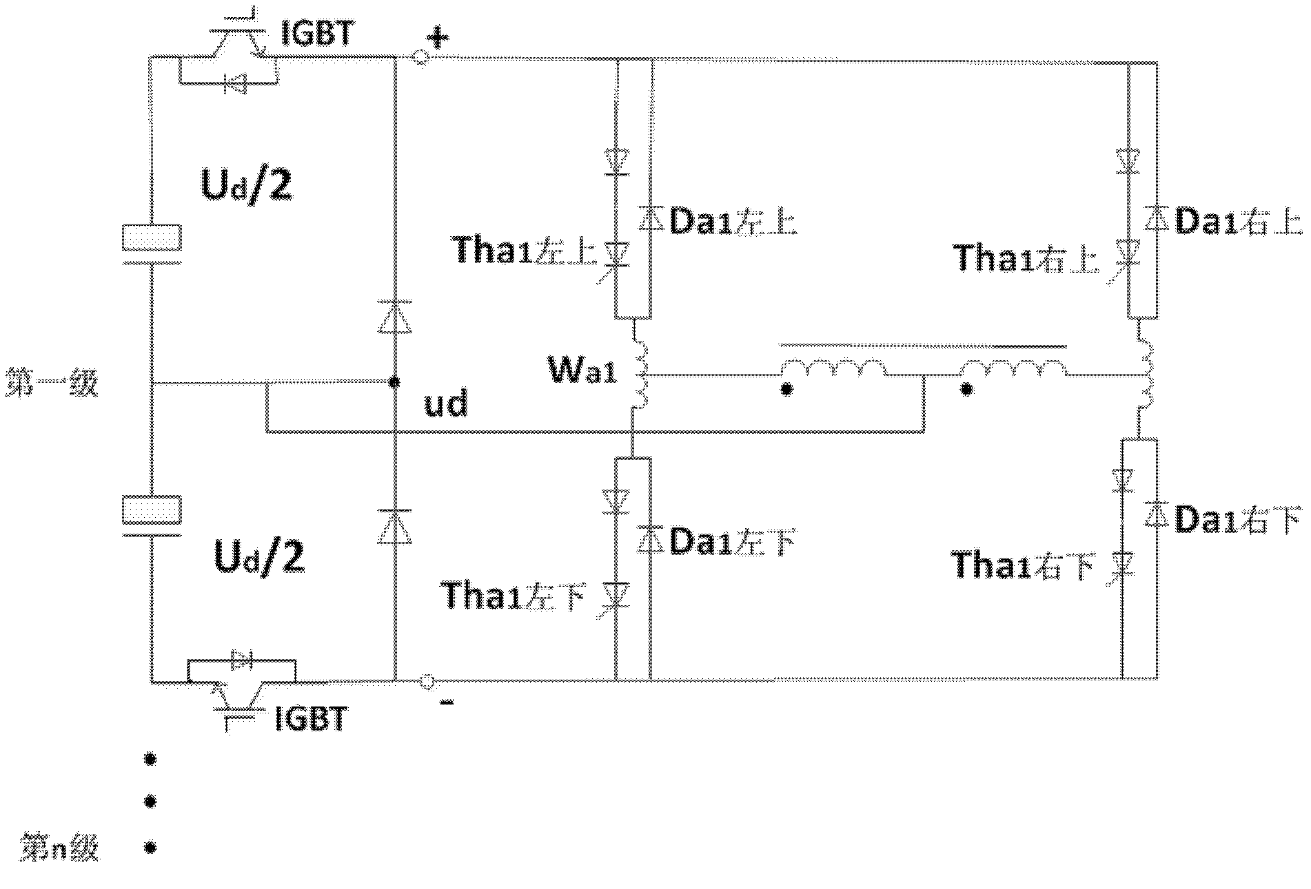
[0017] The circuit diagram of this specific embodiment is as figure 1 as shown. The inverter works according to the intermediate frequency square wave. Each set of diagonal bridge arms works 180° in turn. When commutation is required, for example, from the upper left and lower right diagonal bridge arms to the lower left and upper right diagonal bridge arms, the commutation process of the inverter is as follows: first, the chopper in the voltage divider is turned off Switch the IGBT so that its output DC voltage ud instantaneous value is zero. Simultaneously add the commutation voltage pulse ΔU(u Wa1 ), each commutation voltage positive pulse is a wave with an amplitude ≈+5~10v (subject to the commutation speed), and a pulse width ≈the calibrated turn-off time of the thyristor is about 100μs. Positive u Wa1 The value represents that the polarity of the voltage on Wa1 is up positive and down negative. The direction of ΔU is always helpful for commutation. These voltages ...

specific Embodiment 2

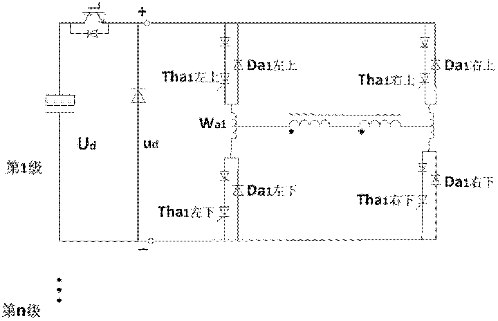
[0021] Specific embodiment 2 (as figure 2 shown):

[0022] Compared with the specific embodiment 1, the difference is that each group of transformer coils no longer leads to a midpoint, and each group of voltage regulators has no midpoint, so only one chopper switch in each group of voltage transformers can be used. or can still be used with figure 1 same without eliciting the midpoint.


PUM


Abstract

The invention relates to power electronic science in electrochemical engineering and aims at providing a direct current electron voltage-dividing voltage regulator used for sharing a voltage by utilizing an intermediate frequency transformer. The voltage-dividing voltage regulator comprises n voltage dividers which are same in structure, each voltage divider is provided with two electrolytic capacitors which are connected into a group in series, and the positive terminal and negative terminal of each voltage divider are respectively connected with a chopper switch. The output of the voltage divider is respectively connected with the input end of an inverter, and the structures of the inverters in different stages are the same; the output end of each inverter is connected to a coil of the intermediate frequency transformer, the middle point of the coil is connected to that of a double-electrolytic capacitor, and the coils connected with the output ends of the inverters in different stages are all wound onto the same iron core. By applying the direct current electron voltage-dividing voltage regulator provided by the invention, a higher direct current voltage can be divided into multiple lower adjustable direct current voltages uniformly or in specified proportion. The voltage divider has higher efficiency, thus being applicable to high-power occasions. Direct-current output currents can be nonuniform in certain degree, and the alternating current of low frequency or high frequency component can be contained in certain limit.

Description

technical field [0001] The invention belongs to the discipline of electric power electronics, and in particular relates to a direct current electronic voltage dividing voltage regulator utilizing an intermediate frequency transformer for voltage equalization. Background technique [0002] At present, the DC voltage divider used for signal acquisition mostly adopts resistor divider, that is, two or more resistors are connected in series to a DC voltage, or a potentiometer is commonly used for voltage divider. Each or each section of resistance is divided into a part of the voltage to form a voltage divider. This voltage divider has low efficiency and is suitable for signal acquisition or low power use, but not for high power applications. Another method suitable for high power is to convert DC into AC first, then use transformers to convert into several groups of AC, and then rectify into several groups of DC. This method equipment is complicated, and cost is high. Conten...

Claims


Application Information

Patent Timeline
Patent Type & Authority Patents(China)
IPC IPC(8): H02M3/28H02M3/315
Inventor 汪隽迈汪槱生顾诚诚
Owner 汪槱生
Features
  • R&D
  • Intellectual Property
  • Life Sciences
  • Materials
  • Tech Scout
  • Unparalleled Data Quality
  • Higher Quality Content
  • 60% Fewer Hallucinations
Learn More