Vector control apparatus and motor control system

A vector control, motor technology, applied in vector control system, motor control, motor generator control and other directions, can solve the problem of not being able to correctly estimate the shaft error and so on

Inactive Publication Date: 2012-03-21
HITACHI IND EQUIP SYST CO LTD
View PDF5 Cites 13 Cited by
  • Summary
  • Abstract
  • Description
  • Claims
  • Application Information

AI Technical Summary

Problems solved by technology

However, the saturation characteristic of inductance obtained by superimposing high frequencies is a nonlinear characteristic, and it is difficult to model it with a function such as a sine wave as in the case of saliency
Therefore, transitional axis errors cannot be correctly estimated, and the same problem arises

Method used


Image

  • Vector control apparatus and motor control system
  • Vector control apparatus and motor control system
  • Vector control apparatus and motor control system

Examples


no. 1 approach

[0067] Hereinafter, embodiments of the present invention will be described in detail with reference to the drawings.

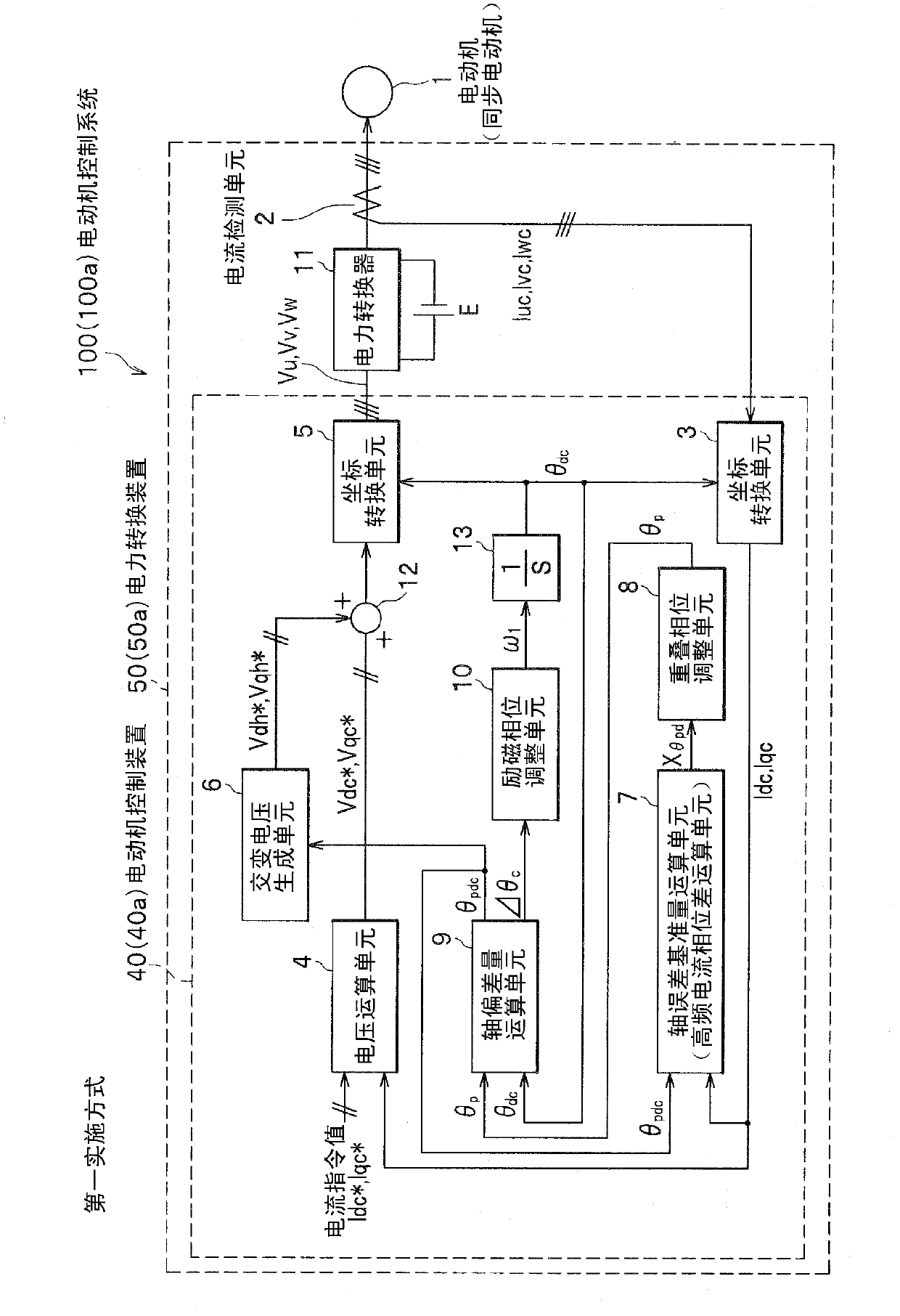
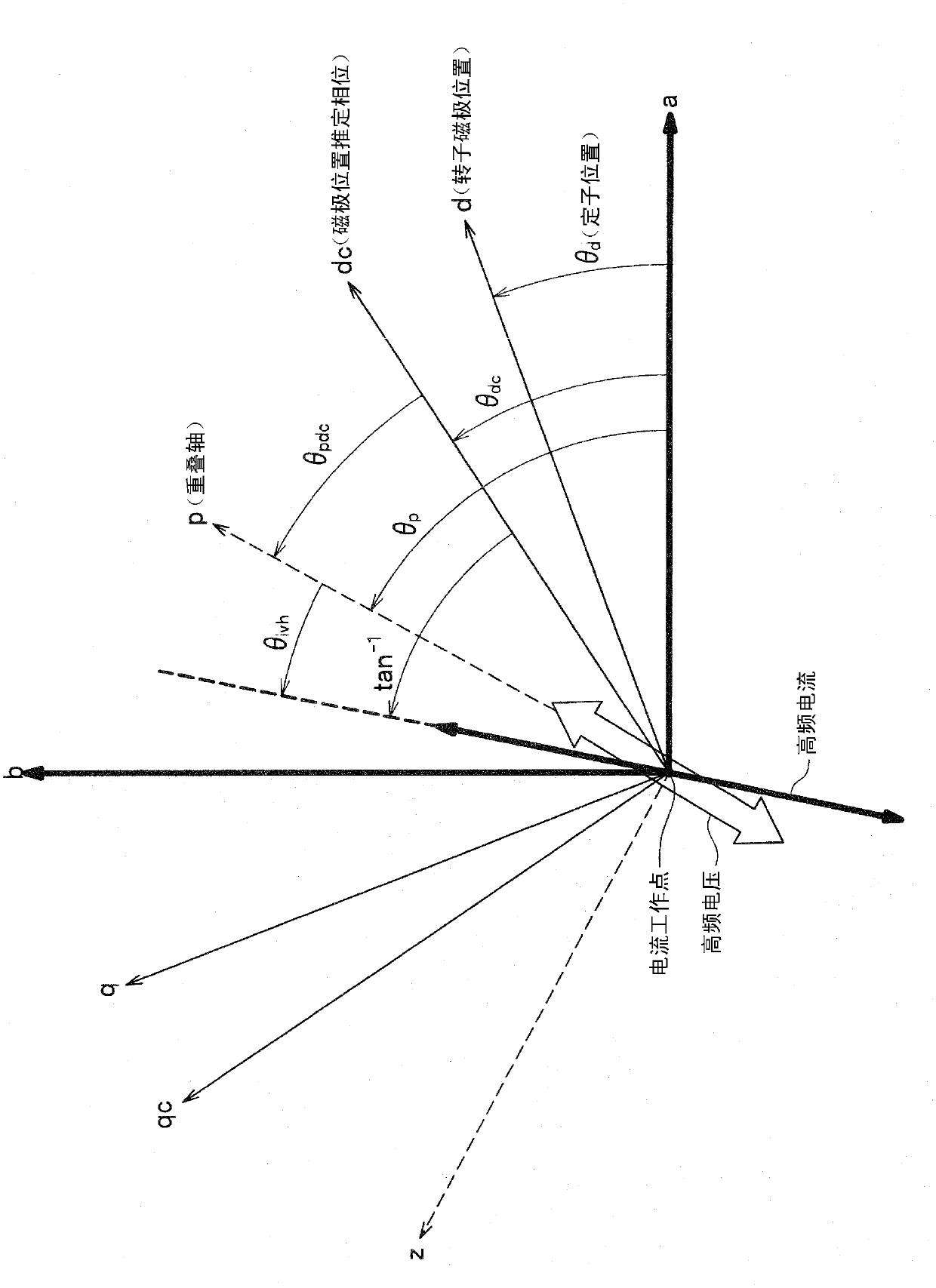
[0068] figure 1 is a configuration diagram of a motor control system according to the first embodiment of the present invention; figure 2 It is a diagram showing the definition of the coordinate system and symbols used in motor control.

[0069] exist figure 1 Among them, the motor control system 100 has a power conversion device 50 and a motor 1 , and the power conversion device 50 ( 50 a ) has a motor control device 40 ( 40 a ), a power converter 11 and a current detection unit 2 .

[0070] The current detection unit 2 detects three-phase currents Iu, Iv, and Iw flowing in the motor 1, and outputs three-phase current signals Iuc, Ivc, and Iwc. Power converter 11 converts DC power from DC power supply E into three-phase AC power based on three-phase command voltages Vu, Vv, and Vw generated by motor control device 40 , and supplies the three-phase AC powe...

no. 2 approach

[0133] Figure 10 It is a configuration diagram of a motor control system according to a second embodiment of the present invention.

[0134] and figure 1 Compared with the configuration of the motor control system 100c of this embodiment, the second shaft deviation calculation unit 101 that estimates the shaft deviation Δθ (= θpd) from the induced voltage of the motor 1 is added, and the excitation phase adjustment unit 10 is changed to give Either one of the axis deviation calculation unit 9 and the second shaft deviation calculation unit 101 is selected as the excitation phase switching adjustment unit 102 for the switching function of the shaft deviation. Since the axis deviation amount after switching is Δθh, the symbol of the output signal of the axis deviation amount calculating means 9 is changed to Δθh. The second axial misalignment calculation unit 101 estimates the axial misalignment Δθemf by (Formula 10) using the characteristic parameters of the electric motor. ...

no. 3 approach

[0145] In each of the embodiments described above, although a synchronous motor was used as the motor, an induction motor can also be used.

[0146] Figure 13 It is a configuration diagram of a motor control system as a third embodiment of the present invention.

[0147] The motor control system 100 d is different from the first and second embodiments in that an induction motor 131 is used instead of the motor 1 and a slip compensation unit 132 and an adder 14 are added.

[0148] In the case of the induction motor 131, although there is no saliency due to the shape of the rotor, the saliency of the inductance is equivalently exhibited due to the magnetic saturation phenomenon caused by the secondary magnetic flux excited by the induced current on the primary side Therefore, the method of the first embodiment can be used. That is, since the rotor (not shown) of the induction motor has no magnets, the phase adjustment unit 8 ( Figure 5 ) only needs to make the d-axis follow...


PUM


Abstract

The invention provides a vector control apparatus and a motor control system, comprising a alternating voltage generating unit that resolves alternating voltage with frequency different from that of motor current into magnetic-excitation axis voltage component and torque axis voltage component and performs superposition; a high-frequency-current phase difference computing unit that computes phase difference between high-frequency current and alternating voltage Vdh*, Vqh* by subtracting phase (arctan (Delta Iqc/Delta Idc), or arctan (Delta Ibc/Delta Iac))of superimposing axis from phase of high-frequency current generated in motor current by alternating voltage; a superimposing axis adjusting unit that adjusts phase direction of superimposing axis such that phase difference computed by high-frequency-current phase difference computing unit becomes zero; an axis deviation amount computing unit that computes axis deviation amount between superimposing axis whose direction has been adjusted by superimposing adjusting unit and magnetic-excitation axis; and a magnetic-excitation axis adjusting unit that adjusts phase direction of magnetic-excitation axis such that axis deviation amount becomes zero.

Description

technical field [0001] The present invention relates to a vector control device and a motor control system for controlling a motor based on a high-frequency current generated by superimposing a high-frequency voltage. Background technique [0002] In drive systems of AC motors such as synchronous motors and induction motors (hereinafter referred to as "motors"), a power conversion device typified by an inverter is often used as a motor drive device. [0003] A power conversion device for driving a motor that requires high performance needs to detect rotor control information such as the rotor position and rotational speed of the motor with high precision. In recent years, power conversion devices have used a method of attaching a position sensor or a speed detector to the motor to estimate the control amount with high accuracy based on the back electromotive force information generated by the motor without actually measuring the rotation angle. However, the method of estima...

Claims


Application Information

Patent Timeline
Patent Type & Authority Applications(China)
IPC IPC(8): H02P21/14H02P6/18H02P6/06H02P6/08H02P6/182H02P6/185H02P6/28H02P21/00H02P21/06H02P21/18H02P21/22H02P21/24H02P21/26H02P23/00H02P23/07H02P23/08H02P23/12H02P23/14H02P27/04
CPCH02P21/04H02P21/146H02P6/183H02P21/18H02P21/26H02P2203/11
Inventor 荒川阳一郎金子大吾岩路善尚小沼雄作
Owner HITACHI IND EQUIP SYST CO LTD
Why Eureka
Try Eureka