
Gas dehydration and dealkylation method for supersonic vortex tube

A vortex tube and supersonic technology, which is applied in the direction of gas fuel, separation methods, chemical instruments and methods, etc., can solve the problem that the gas-gas heat exchanger cannot fully exchange heat and make full use of the cooling capacity, and the pressure difference between the inlet and outlet of the supersonic vortex tube and other problems to achieve the effect of preventing overpressure explosion or leakage of raw material gas, ensuring smooth operation, and preventing blockage

Active Publication Date: 2012-03-28
PETROCHINA CO LTD
View PDF13 Cites 12 Cited by
  • Summary
  • Abstract
  • Description
  • Claims
  • Application Information

AI Technical Summary

Problems solved by technology

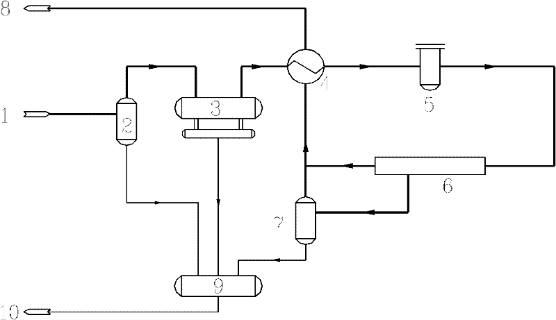
[0032] It can be seen from the above process flow that in order to avoid the formation of hydrates, the temperature of the natural gas before entering the supersonic vortex tube 6 cannot be lower than the hydrate formation temperature, so the gas-gas heat exchanger 4 cannot fully exchange heat and make full use of the cooling capacity
In addition, since the temperature of the feed gas in the outlet gas heat exchanger 4 cannot be lower than the hydrate formation temperature, a larger pressure difference between the inlet and outlet of the supersonic vortex tube is required to obtain a lower dew point temperature

Method used


Image

  • Gas dehydration and dealkylation method for supersonic vortex tube
  • Gas dehydration and dealkylation method for supersonic vortex tube
  • Gas dehydration and dealkylation method for supersonic vortex tube

Examples


Embodiment Construction

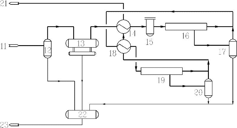
[0045] The implementation of two-stage (or multi-stage) supersonic vortex tube technology is illustrated by taking the dehydration of high-pressure natural gas with two-stage supersonic vortex tube as an example.

[0046] The inlet pressure of raw natural gas is 10MPa, and its specific composition is shown in Table 1.

[0047] Table 1 Example raw material natural gas composition table

[0048]

[0049]According to the calculation, the hydrate formation temperature of this raw natural gas is 16.35°C. In order to prevent hydrate from clogging the gas-gas heat exchanger, the inlet temperature of the first-stage supersonic vortex tube is set at 20°C.

[0050] Its process is as figure 2 shown.

[0051] Containing saturated water and a small amount of free water, the raw material gas 11 with a pressure of 10.0MPa and a temperature of 30°C first enters the raw gas separator 12 and the raw gas filter separator 13 to remove large particles respectively to reduce abrasion under hi...


PUM


Abstract

The invention relates to a gas dehydration and dealkylation method for a supersonic vortex tube, wherein the feed gas enters a separator and a filter separator to separate large particles out, the filtering separated feed gas and a dry gas are cooled in a first level gas-to-gas heat exchanger, and enter a first level prewhirling pre-nucleation supersonic vortex tube to be dehydrated after fine and small solid particles are separated out through a fine filter, and are separated into a first level dry gas and a gas-liquid mixture; the gas-liquid mixture enters a first level gas-liquid separatorto be separated; the separated gas phase flows into the first level dry gas to enter a second level gas-to-gas heat exchanger; the cooled first level dry gas enters a second level prewhirling pre-nucleation supersonic vortex tube to be dehydrated, and is separated into a second level dry gas and the gas-liquid mixture; the gas-liquid mixture enters a second level gas-liquid separator to be separated; the separated gas phase is interflowed with the second level dry gas to enter the second level gas-to-gas heat exchanger and the first level gas-to-gas heat exchanger for exchanging heat with thefirst level dry gas and the feed gas for temperature rise, and the heated dry gas is exported; and the high water dew point and blockage problems of hydrocarbon are solved, the dehydration and the dealkylation of the feed gas are realized, and a purification device is ensured to stably operate.

Description

Technical field: [0001] The invention relates to a supersonic vortex tube gas dehydration and dehydrocarbon method. Background technique: [0002] Supersonic vortex tube dehydration technology, the main research and development companies are Translang and Twister. [0003] The main patents formed are as follows: [0004] 1.《Supersonic separator apparatus and method》 [0005] (US6776825B2) [0006] 2. "Method of and apparatus for the separation of components of gas mixtures and liquefaction of a gas" [0007] (US6372019B1) [0008] 3. "Nozzle for supersonic gas flow and an inertia separator" [0009] (US6513345B1) [0010] The main supersonic vortex tube patents formed (applied) in China are as follows: [0011] 1. "Cone Core Supersonic Condensation Cyclone Separator" [0012] (CN200810011258.6) [0013] 2. "A Supersonic Swirling Condensation Combined Nozzle" [0014] (CN200610105199.X) [0015] 3. "Multi-inlet Supersonic Swirl Separation and Backpressure Device" ...

Claims


Application Information

Patent Timeline
IPC IPC(8): B01D53/26B01D45/16B01D50/00C10L3/10
Inventor 计维安高晓根黄黎明陈胜永常宏岗宋彬熊钢
Owner PETROCHINA CO LTD
Learn More